logo elektroda
logo elektroda
X
logo elektroda

Retro features: the Polish UCY74xx series from CEMI – an overview of sample logic gates

p.kaczmarek2 3720 59

TL;DR LABEL_AI_GENERATED

  • A practical overview of Polish CEMI UCY74xx TTL logic gates covers NAND, NOR, NOT, AND, and AND-OR-INVERT chips.
  • Each circuit is explained with Boolean equations, truth tables, and button-driven video demos, including open-collector and buffered output variants.
  • Examples include UCY7401, UCY7402, UCY7404, UCY7406, UCY7407, UCY7408, UCY7410, UCY7420, UCY7430, UCY7450, and UCY7451; UCY7406 can switch loads up to 30V.
  • The demonstrations show LEDs responding exactly to the logic tables, such as a single button for UCY7402 and either button pair for UCY7450.
  • The selection is not exhaustive, and more complex sequential and combinational UCY circuits are promised in a later post.
AI summary based on the discussion. May contain errors.
ADVERTISEMENT
Treść została przetłumaczona polish » english Zobacz oryginalną wersję tematu
Listen:
  • 74154-based spectrum analyser with 16 LED bars

    #31 21945441
    robert nawrot
    Level 21  
    Posts: 515
    Help: 31
    Rate: 111
    I built a spectrum analyser (with flashing LED bars) based on the 74154 for my amplifier. The board featured 16 band-pass filters, switching transistors and a transistor-based drive level indicator. The 74154 switched the filters and the ‘bars’ sequentially. The circuit was controlled by a 7490 counter.
    It worked a treat, and I spent four of my school grants on the yellow rectangular LEDs – 16 × 10 LEDs. A nod to the 1980s :)
  • ADVERTISEMENT
  • Odra 1325 control unit used over a dozen kilograms of ICs

    #32 21945474
    bratHanki
    Level 39  
    Posts: 5783
    Help: 457
    Rate: 1415
    The successor to the Odra 1325 at our workplace was reportedly to be the Mera 400, which was physically on site but, during my two-and-a-half-year tenure, was only ‘tested’ – that is, it was fed the same data as the Odra, and the results were then compared.
    As for the number of circuits in the Odra, the figure given by AI is plausible, as the control unit itself contained over a dozen kilograms of packages with integrated circuits, and in addition there werefour cabinets with a volume of over 1 m³, packed to the ceiling with similar packages. Added to this was the memory, namely several rewinders with 1/2" magnetic tape.
    Digital displays were still of the 3½-digit panel type, e.g. CPO3515 and CPO4507.
  • Questioning MTBF of Cemi-based computers

    #33 21945479
    kris8888
    Level 41  
    Posts: 7122
    Help: 537
    Rate: 1938
    bratHanki wrote:
    As for the number of circuits in the Oder, the figure given by AI is plausible, as the control unit itself contained over a dozen kilograms of integrated circuit packages

    If there really were that many chips, then I have the utmost respect for the technicians who diagnosed and repaired any faults in these computers. Just locating a faulty package would probably have required a solid understanding of the design and operation of the whole system.

    I wonder what the MTBF was for these computers, assuming they mainly used Polish TTL chips from Cemi.
  • #34 21945520
    buszyl33
    Conditionally unlocked
    Posts: 782
    Help: 58
    Rate: 185
    Well, here’s the fly in the ointment. A company in Pruszków (I can’t remember the name) used to manufacture control systems for CNC lathes. The problems – and I mean PROBLEMS – began when they started replacing the Texas chips with CEMI :(
  • Military-grade UCY64xx rumor and test sorting claim

    #35 21945545
    sq3evp
    Level 39  
    Posts: 6764
    Help: 228
    Rate: 908
    I’ve heard from electronics professors that the UCY64xx series were the better (UCY) versions designed for military use.
    This could well be true, as one of the professors was a graduate of the Military University of Technology (WAT).

    The rumour was that they would cut out a ‘Dirac pulse’ from the Gaussian distribution curve – the ones with that were for the military, and the rest for civilian use. These were the ones that scored 100 per cent in tests (the purest silicon wafers and other parameters).
  • Chip-level fault isolation and replacement on module systems

    #36 21945559
    bratHanki
    Level 39  
    Posts: 5783
    Help: 457
    Rate: 1415
    kris8888 wrote:

    If there really were that many of these systems, then I have the utmost respect for the technicians who diagnosed and repaired any faults in these computers. Just pinpointing a faulty module must have required a thorough understanding of the design and operation of the whole system.

    As support staff, we had a whole cupboard full of spare modules. These were swapped out in the event of a fault, and usually after a few attempts the system would boot up, whilst the faulty unit would end up in the ‘defective’ cabinet.
    On one occasion, the fault was more serious, so the company called out a technician. An unassuming chap turned up, with a face that looked exactly like nobody’s, said hello, ran one of his service programmes and watched to see where it would stop. On that basis, with the help of a large manual, he located the chip and the faulty component.
    Repair: he cut out the chip with small nippers, then removed the remains of the legs with tweezers and a soldering iron, cleared the holes with a sharpened match and soldered in a new chip. All in all, it took about two hours, but it was clear that the bloke was paid by the hour rather than ‘by the job’ . The best part of it all was that we were entitled to 3 litres of denatured alcohol every quarter for cleaning the contacts. :-)
    PS. As far as I can remember, I think all the chips on the packages were grey, whilst the CEMI production ones were black...
  • TTL-based logic in MDS442 and Odra 1305

    #37 21945633
    Stanley_P
    Level 28  
    Posts: 1332
    Help: 62
    Rate: 294
    kris8888 wrote:
    It wasn’t just the ‘Koncert’ that had a ‘controller’ based on TTLs. The MDS442, or the popular ‘drawer’, also had its entire logic based on TTLs. On top of that, it had a monolithic UL7505 regulator in a TO-3 metal casing.

    I imagine the Koncert wasn’t an exception; I just haven’t serviced any of the ‘drawers’ (anymore). I was actually referring to that RS flip-flop, which marked the start of my TTL adventure, and which was by no means a rarity in the designs of that era – quite the opposite, in fact ;-)
    kris8888 wrote:
    The Odra 1305 computer was based entirely on TTL circuits. It was a 24-bit machine. Building such a computer today would therefore be nothing groundbreaking. Apart from the fact that it would take up a great deal of time and money.

    That’s exactly what I think too. But as the saying goes, ‘who’s going to stop a rich man?’. Hobbies vary, and as we know, there’s no limit to how much one spends on them, and I don’t argue with that, as long as the passion doesn’t harm anyone else, the environment, and so on. I’m referring all the time to THIS post . Written almost exactly two years ago; at the time, construction was expected to take another three years. So, if my calculations are correct and everything goes according to plan, in about a year’s time the world should see the result ;-)
    Janusz_kk wrote:
    This particular project is in a league of its own compared to a calculator. The bloke came up with a brilliant idea; I downloaded the design for this processor <...>
    The entire state machine is on EPROMs.

    Perhaps it’s in a league of its own, perhaps he came up with a brilliant idea. Maybe I’ll have a look at it during the long winter, though I rather doubt it. However, to cut a long story short: this thread is technically about logic gates from CEMI, i.e. not even the entire TTL family, and certainly not about EPROMs ;-)
    gregor124 wrote:
    And by the way, if anyone remembers the AMIGA home computer, this is what the prototype built using TTL chips looked like.

    According to this article:
    http://retroszpuntafan.pl/historia-amigi/czesc-3-pierwszy-prototyp/
    However, the ‘heart’ of the prototype was a ‘standard’ 68000 processor, which, according to ejaj, contains around 68,000 transistors (a coincidence with the processor’s symbol, apparently used for marketing purposes at the time). Specialised circuits were prototyped on TTL ‘chips’. I reckon that if the processor (?) had been included too, there would have been a looooot more of it.
    bratHanki wrote:
    As support staff, we had a whole cupboard full of spare modules. These were swapped out in the event of any fault <..>

    We serviced the electronics of the aforementioned machine tools in such a way that every electronics technician (there were several repair teams) carried a set of working spare kits with them, as well as a few handfuls of the integrated circuits and other components contained within them, basic tools such as a desoldering pump (matches too, I think ;-) ), a soldering iron, wire cutters, a multimeter, an oscilloscope, etc. There was no formal service programme; in any case, the issues were likely on a much smaller scale, and we would initially pinpoint the fault area by swapping modules. Next, an attempt to repair the faulty package on the spot, the aforementioned checking of chip temperatures with your fingers, blind replacement of the Tesla, etc. If that didn’t work, we’d try methods such as deduction, analysing the circuit diagram, signal measurements, etc., provided, of course, that time allowed. If the on-site repair failed, we’d use one from the set of working The service parts remained in the machine, whilst the faulty one was taken by the electronics technician to the ‘base’ – which was the factory where the machine tools in question were manufactured – and was repaired there without any fuss.
    Spirytus, as you reminded me, was there too; consumption, of course, strictly according to the allocation ;-) , and that bloke who was unlike anyone else was the spitting image of me ;-)
    I’ll just add that the machine tool’s electronics also included an analogue section for motor control; I can’t quite remember now – I think there were operational amplifiers, and the power components were probably thyristors, but that’s another story.

    Anyway, it was nice to reminisce; the thread’s author really knows how to stir up emotions ;-) TTLs are a thing of the past for me, though I wonder if they’re still used in any new devices currently being manufactured. Ejaj’s on about the military and industry in certain situations, but I don’t blindly believe him on that.
  • Weekly crashes on Mera 9150 from disk errors

    #38 21945638
    Janusz_kk
    Level 39  
    Posts: 5886
    Help: 229
    Rate: 1482
    kris8888 wrote:
    I wonder what the MTBF was for these computers, assuming they mainly used Polish TTL chips from Cemi.

    For ‘my’ Maryśka (Mera 9150), it was about a week; the computer would crash and you’d have to recover the data using AFL* onto tape.
    Most often it was a critical disk error; the operating system was rubbish, super-resilient to errors from the tape – it could ‘churn through’ the tape endlessly – yet a single read error from the disk would bring the whole thing crashing down.
    After the crash, cleaning the contacts and running tests, the system was rebuilt from scratch – first the core, then the libraries – after which the ladies could start entering data, whilst the data recovered by AFL was being read in simultaneously. This took a good day.

    *AFL was a specialised system that loaded solely into memory, identified data on the disk and automatically wrote it to tape.
  • #39 21945656
    kris8888
    Level 41  
    Posts: 7122
    Help: 537
    Rate: 1938
    Stanley_P wrote:
    blind replacement of a Tesla

    And were those Czechoslovakian Teslas more prone to faults than the Cemi circuits?

    I’m just asking out of curiosity, because I actually had to replace one TTL-based counter in my Meratronik recently – it happened to be a Tesla as fitted from the factory.
  • ADVERTISEMENT
  • Tesla TTL chips were often a hit-or-miss replacement

    #40 21945674
    Stanley_P
    Level 28  
    Posts: 1332
    Help: 62
    Rate: 294
    kris8888 wrote:
    And were those Czechoslovakian Teslas more prone to breakdowns than the Cemi systems?

    Let me quote myself again:
    Stanley_P wrote:
    The second quick method: if a Czechoslovak-made Tesla TTL chip was on the faulty panel, replacing it blindly often meant ‘hit or miss’. I’ve no idea why that was the case; perhaps the Tesla components were already starting to leak back then? ;-)

    I learnt this from more experienced colleagues with whom I worked at that repair shop. And indeed, the ‘Tesla method’ often worked.
    As for how it actually was – that is, if you were to compare a large batch of Teslas, CEMIs or other makes (say, from the former Eastern Bloc) – I’ve no idea. Perhaps it applied to certain batches from a particular period, and so on.
    Looking back now, I’ve been wondering why, in the control systems of those machine tools – which very often operated in harsh conditions, ranging from sweltering heat in the workshops to near-freezing temperatures, certainly far harsher than the aforementioned Odra or Mera machines – why TTLs with enhanced specifications, such as the UCA or those starting with a 6, weren’t used. As far as I recall, they were the most ordinary UCY 74xx chips and a mix of equivalents from various countries of origin (though I think they were all from the Eastern Bloc). But as I’ve already mentioned, those were times of widespread shortages of everything – not to mention foreign currency – and they probably just used whatever they could get their hands on at the time, just to meet the quota.
  • #41 21945688
    gregor124
    Level 29  
    Posts: 1729
    Help: 103
    Rate: 893
    >>21945633
    I don’t know why they would have made a 68000 in TTL if they weren’t manufacturing it themselves, and given that Apple forced Motorola to cease its monopolistic practices, they could have bought it for the price of a dozen or so TTL chips?
    In any case, a prototype of one of the later chips in the 68k family – the 68030 – was built using TTL, and it ‘fit’ onto 18 PCBs; it was built not only using TTL, but also GAL/PAL and memory chips.
    Besides, it’s a mystery why this processor needed as many as 68,000 transistors, when an ARM1 made do with 25,000 and outperformed both the 68000 and the 80386.
    Sometimes I get the impression that all these computers were built without any real concept or thought behind them, and that the designers were paid based on the number of wasted chips ;) .
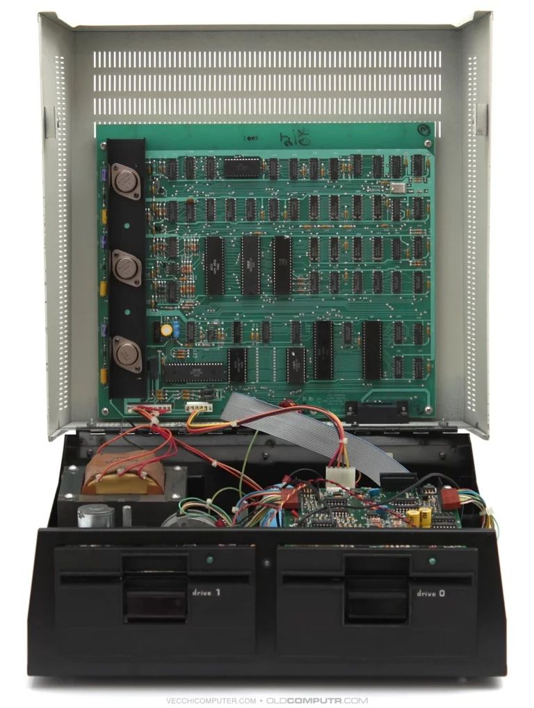
    Here’s an example:
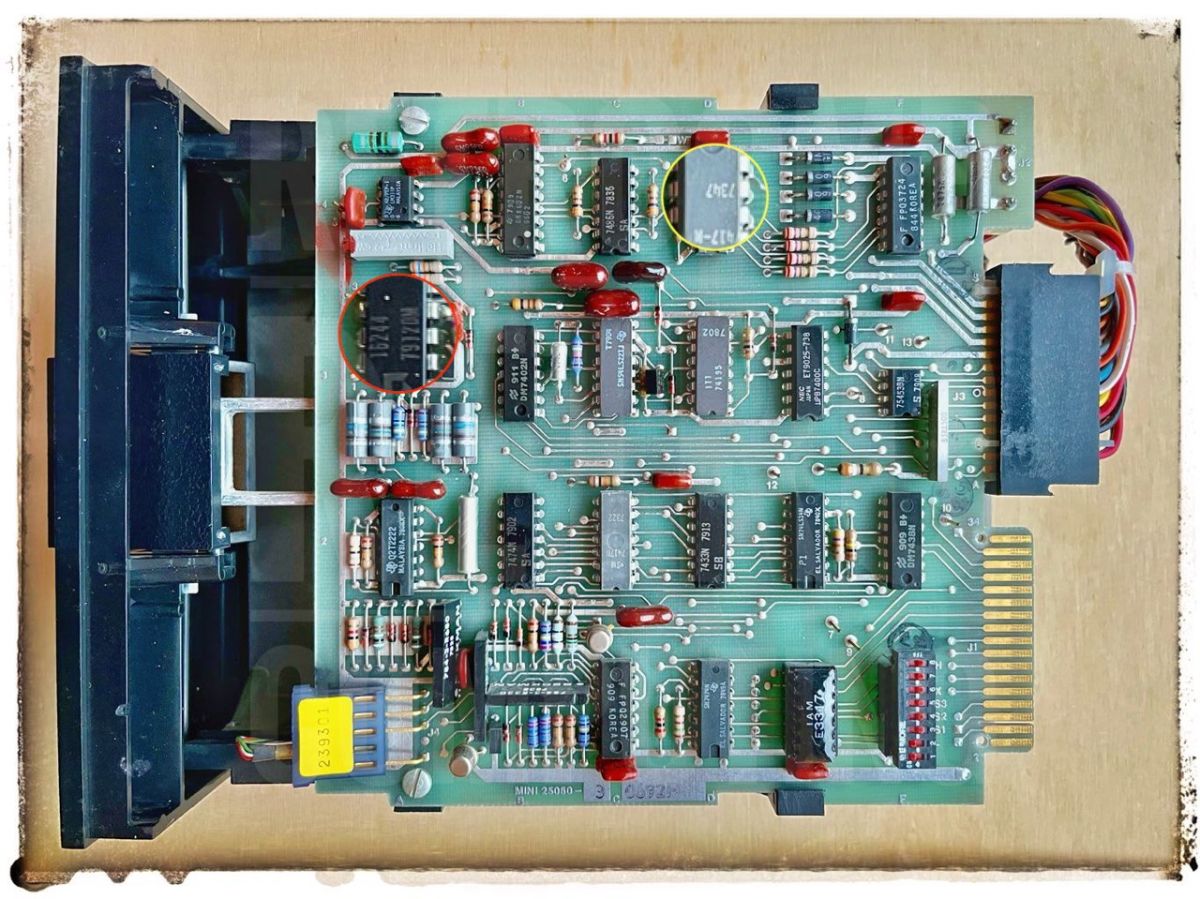
    A disk drive for several systems.
    CP/M, circa 1977:
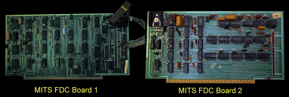
    Retro features: the Polish UCY74xx series from CEMI – an overview of sample logic gates
    Plus this FDD controller:
    Retro features: the Polish UCY74xx series from CEMI – an overview of sample logic gates
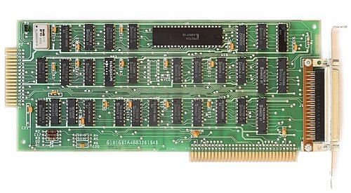
    IBM, 1982 – the same:

    Retro features: the Polish UCY74xx series from CEMI – an overview of sample logic gates

    Retro features: the Polish UCY74xx series from CEMI – an overview of sample logic gates

    Commodore 8050 – expensive and insanely pricey ;)
    Retro features: the Polish UCY74xx series from CEMI – an overview of sample logic gates

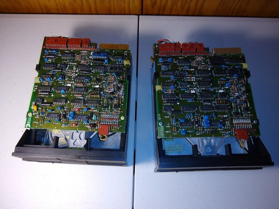
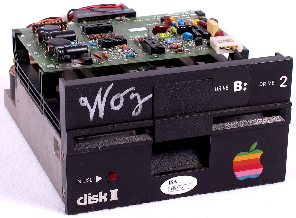
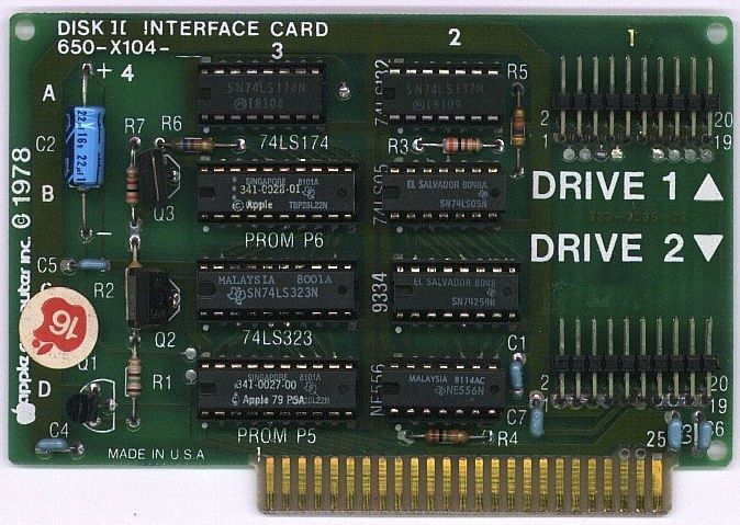
    And for comparison, the Apple II, 1978:
    The drive is practically the same as the one in the first photo, after discarding all the unnecessary electronics and replacing them with a simple circuit board containing signal amplifiers.
    Retro features: the Polish UCY74xx series from CEMI – an overview of sample logic gates
    And a controller supporting up to two drives, built using two 256-byte PROM chips and several TTL chips.

    Retro features: the Polish UCY74xx series from CEMI – an overview of sample logic gates

    There is also the well-known story of the Atari game Breakout, where Atari’s designers used 120 TTL chips, whilst Wozniak, in just two days and without access to the documentation, designed an equivalent version that required 42 chips, and ultimately 44, because Jobs insisted that the end credits be displayed at the top of the screen, just as in the original Atari design ;) .
    Helpful post? Buy me a coffee.
  • #42 21945705
    Stanley_P
    Level 28  
    Posts: 1332
    Help: 62
    Rate: 294
    gregor124 wrote:
    I don’t know why they’d make the 68000 in TTL if they weren’t manufacturing it,

    I don’t know why either; I was just responding to what you wrote:
    Quote:
    By the way, if anyone remembers the AMIGA home computer, this is what the prototype built on TTL chips looked like.

    which suggests the whole thing was built using TTLs. Perhaps it was a mental shortcut ;-)
    As for the rest, I won’t comment – I wasn’t interested in the history of computers, processors, games, etc.
    All I can say is that I owned an Amiga 500 for a while, and was happy with it at the time. But that’s a bit off-topic again, and it takes us back to the days when one was young and beautiful, and now only the ‘and’ remains ;-)
  • #43 21945814
    LEDówki
    Level 43  
    Posts: 9690
    Help: 1327
    Rate: 2616
    There was a book by Włodzimierz Sasal called *Digital Circuits of the UCA and UCY Series*. As well as static and dynamic parameters and temperature ranges, it also included diagrams of example circuits, such as a lost-pulse detector.
  • Pruszków CNC controls and early robot arm memory

    #44 21945826
    Stanley_P
    Level 28  
    Posts: 1332
    Help: 62
    Rate: 294
    buszyl33 wrote:
    Well, here’s the fly in the ointment. A company in Pruszków (I can’t remember the name) used to manufacture control systems for CNC lathes. The problems – and I mean PROBLEMS – began when they started replacing the Texas Instruments chips with CEMI

    I hadn’t noticed this post before. So, here’s the rest of my machine tool memories. Indeed, the control systems on the machines I serviced probably came from Pruszków. I don’t know how things stood with those problems after Western circuits were replaced with domestic ones and/or those imported from the Eastern Bloc, as I was already working during the twilight years, in the second half of the 1980s.
    However, your mention of Pruszków has reminded me of an incident. The company that manufactured those control systems – I can’t recall the name either – was, I think, also carrying out some experimental work. They invited us service engineers from the machine tool factory to a training course which concerned – I’m not sure how to put it neatly, as I’m out of the loop on these topics – an industrial robot arm. Oh, something like the first thing that pops up when you Google this image. Only a real, solid chunk of metal
    https://3dexport.com/pl/3d-model-industrial-robot-arm-233743
    The way it worked was that this thing stood in the middle between two lathes manufactured at ‘my’ plant; it would pick up parts from a hopper and load them into the machine. Once machining was complete, it would remove them and place them where required. Without any human intervention...
    Well, unless something went wrong; we were told, for example, that sometimes when the machine’s door wouldn’t open (they were sliding doors which, when operated normally by a human, protected the operator whilst the workpiece was being machined), the arm would sometimes crash through the glass with the workpiece ;-)
    Even so, for us back then it was like something out of this world :-)
    On the control side, everything was certainly still based on TTLs; there were no microprocessors. However, I think there was already something of a ‘computer’ architecture; the course lecturer (probably one of the designers) mentioned something about addressing and so-and-so-bit words. There was certainly ferrite core memory too. As far as I can recall, the course was intended as an introductory programme prior to rolling out these robotic arms into larger-scale production. But whether that ever happened, or whether it remained merely at the experimental stage, I have no idea. My stint with machine tools soon came to an end; the turn of the 1980s and 1990s arrived, and we all know how the vast majority of companies in the People’s Republic of Poland fared.
  • EPROMs used as fast combinational logic on 286 motherboards

    #45 21945856
    TechEkspert
    Editor
    Posts: 7363
    Help: 17
    Rate: 5726
    Several people who used to work with Odra computers have commented on this thread; the final versions of these computers featured TTL integrated circuits (just like the MERA 400 series). I have never worked on these computers myself, but I have spoken to a few people who used them, which inspired me to put together this material A tour of the Odra computers – computers designed and built in Poland . I’d like to ask anyone familiar with these computers to have a look at the thread, and if you spot any errors or omissions, please feel free to add your comments.

    If you’d ever like to share your experiences from the time you worked with Polish Odra or Mera computers, I’d love for you to record an episode of the elektroda.pl podcast https://www.elektroda.pl/rtvforum/audio.php
    We can get in touch here in this thread or via private message.

    As for EPROMs used as combinational logic circuits, ELWRO carried out experiments producing AT motherboards for the 286, where EPROMs with a small capacity of 512x8 but high access speed replaced, for example, PAL/GAL. Below is more information about these prototypes developed in the 1980s.


  • ADVERTISEMENT
  • #46 21945979
    robert nawrot
    Level 21  
    Posts: 515
    Help: 31
    Rate: 111
    I had the complete ODRA 1300 documentation, if my memory serves me correctly – there was a waste paper collection at primary school and someone brought it in. It was a very thick set of documents with diagrams printed on what was practically toilet paper :)
  • #47 21945996
    TechEkspert
    Editor
    Posts: 7363
    Help: 17
    Rate: 5726
    And that’s how counters used to be made – without TTLs and, in fact, without transistors either. AlekZ has posted some interesting material:


  • CEMI TTLs were mostly foreign copies

    #48 21946018
    yorgus_1978
    Level 10  
    Posts: 41
    Rate: 107
    >>21945996
    I reckon they were made using decatrons; in fact, I think there were some on his channel as well.
    As for TTLs, I’m curious whether at CEMI they were only able to churn out circuits from ready-made, licensed or otherwise obtained photomasks, or whether they were capable of designing a circuit themselves and producing something original. Were there any original Polish monolithic integrated circuits? Actually, digital circuits were probably much easier to design than analogue ones, and something like a washing machine controller could easily have been made that way. From what I recall, almost every CEMI circuit was a copy of a foreign one – most often Japanese or French.
  • CEMI-designed MCX1201 and MC1206 circuits

    #49 21946024
    Simon79
    Level 21  
    Posts: 430
    Help: 29
    Rate: 401
    I think the MCX1201 or MC1206 were probably among the very few circuits designed entirely by CEMI.
    I read somewhere that there were apparently ‘original’ circuits produced without a licence, such as the MC14007 calculator chip, but this involved recreating the photomask and adapting the manufacturing process to the technical capabilities of the Polish People’s Republic, using documentation obtained from MPS 7541-007😁, and that the silicon structure bore the inscription ‘ITE CEMI’.
  • ADVERTISEMENT
  • #50 21946061
    music
    Level 28  
    Posts: 1795
    Help: 94
    Rate: 264
    I believe the MC1206s were still being manufactured in Romania. The question is: who was manufacturing them for whom?


    Retro features: the Polish UCY74xx series from CEMI – an overview of sample logic gates
  • Preference for TTL over early 4000-series CMOS

    #51 21946062
    viayner
    Level 43  
    Posts: 10638
    Help: 1563
    Rate: 2055
    Hello,
    I’ve built up quite a collection of TTL and CMOS chips over the years; personally, I’ve always preferred TTL, as the early ‘4000’ series were quite sensitive to rough handling. TTL chips, having a higher current-carrying capacity, were also less susceptible to connection errors. I still use them in my projects; nowadays, in the age of microcontrollers, everything is handled by the microcontroller and hardly anyone knows why or how a particular circuit works, whereas with TTLs there had to be a logical flow of information and an understanding of how they operated. Quite often, there’s already a ready-made 74xx or 40xx chip that solves a given problem. These days, I hardly ever use Polish or Eastern Bloc chips anymore, as they’re unreliable; I stick to ‘Western’ ones. I remember back in the day the Mera printer controller, I think it was the D180 (one of those large, even enormous, 9-pin printers); it was based on an 8080 with TTLs, whilst there were ‘Western’ chips there, everything worked correctly, but using the MCY7880 already caused problems, and the Soviet 8080 was a mistake – its operation was, generally speaking, erratic.
    Returning to the UCY series and its derivatives, as a beginner I had simple ‘00/’10/’20’ gate-type chips, simpler flip-flops, counters and decoders such as the ‘74/’90/’93/’42/’47/’154’ etc. Mostly second-hand, as these were still quite expensive chips. The BOMIS UC series – i.e. substandard chips that didn’t meet all the specifications – worked so-so, depending on the chip, and formed the basis of educational kits available, for example, in scout shops – do you still remember those? :)
    Best regards.
  • Printer driver bug caused every other character to print

    #52 21946084
    Janusz_kk
    Level 39  
    Posts: 5886
    Help: 229
    Rate: 1482
    viayner wrote:
    I remember back in the day, the Mera printer driver – I think it was the D180 (one of those large, even enormous, 9-pin printers) – was based on the 8080

    On the 8080, it was the DZM180, which was rather slow and unreliable; the D180 was an older version using TTLs and Western SRAMs, as Polish ones weren’t available. The memory was used to store the entire line; once it received it, it would print it.
    The DZM 180 on the 8080 was terribly slow and dropped characters; on the Mer 9150, the result was that when it printed library code – and only there – it would print every other character.
    This was the result of the system’s ‘optimisation’; as its developers had fast printers at their disposal, they skipped the checks and waiting for the bus signals, simply sending the code straight to the printer – the old one printed fine, but the new one didn’t. Once I’d discovered this, I’d type a few lines of code into the keyboard buffer and jump from there to the programme printing the libraries.
  • CEMI chip production constraints and CA80 performance

    #53 21946086
    LEDówki
    Level 43  
    Posts: 9690
    Help: 1327
    Rate: 2616
    In 1994 or 1995, satellite tuners manufactured under licence from PaCE were fitted with single TTL chips. The CMOS chips were notoriously prone to damage during the assembly of the tuners. Employees wore wrist straps and clipped themselves to earthed workbenches. There was a Polish name for this tuner; it was manufactured by SAwico Electronics in the former ZRK Kasprzak buildings. They later moved premises and eventually went out of business. There is no employee documentation.
    Projects from CEMI. A certain talented young engineer, following the closure of CEMI, took a job at a secondary school. He revealed that he and his colleagues had once designed a circuit for tuning and storing TV channels on a television set. It never got beyond the prototype stage, as no one managed to integrate the circuit. There were machines for sorting components, there was an embargo, and attempts were made to get round it (I know this from employees and from memoirs published online). It’s easy to complain without taking into account how these people had to work. The factory’s location next to the tram tracks meant that the masks would shift whenever a tram passed by. The embargo, the lack of foreign currency, and so on. Perhaps there were some things they could have done better. The CA80 worked reasonably well on CEMI chips.
  • Romanian MC1206 production and heavy Polish housings

    #54 21946111
    bratHanki
    Level 39  
    Posts: 5783
    Help: 457
    Rate: 1415
    music wrote:
    I believe the MC1206s were still being manufactured in Romania. The question is: who was manufacturing them for whom?

    As a result of the division of specialisation within the Comecon, Romania was reportedly to specialise in electronics, whilst Poland was assigned machine tools. To make matters even more amusing, production output was measured in tonnes rather than in units. As a student, I had the opportunity to undertake a work placement at the Ostrowiec Steelworks construction site. I had the chance to compare the Japanese rolling mill line – whose individual machines were housed in neat casings welded from sheets of varying thicknesses – with Polish products. Our housings were usually cast and therefore heavy. The maintenance cover on the side of the machine alone could weigh several dozen kilograms. It took three workers to fit it – two lifted it, whilst the third tightened the bolts.
  • Pruszków CNC controls and early robot arm memory

    #55 21946154
    buszyl33
    Conditionally unlocked
    Posts: 782
    Help: 58
    Rate: 185
    Stanley_P wrote:
    buszyl33 wrote:
    Well, here’s the fly in the ointment. A company in Pruszków (I can’t remember the name) used to manufacture control systems for CNC lathes. The problems – and I mean PROBLEMS – began when they started replacing the Texas-based systems with CEMI

    I hadn’t noticed this post before. Well then, here’s the rest of my machine tool memories. Indeed, the control systems on the machines I serviced probably came from Pruszków. I don’t know what the situation was with those problems following the replacement of Western circuits with domestic ones and/or those imported from the Eastern Bloc, as I was already working during the twilight years, in the second half of the 1980s.
    However, your mention of Pruszków has reminded me of an incident. The company that manufactured those control systems – I can’t recall the name either – was, I think, also carrying out some experimental work. They invited us service engineers from the machine tool factory to a training course which concerned – I’m not sure how to put it neatly, as I’m out of the loop on these topics – an industrial robot arm. Oh, something like the first thing that pops up when you Google this image. Only a real, solid chunk of metal
    https://3dexport.com/pl/3d-model-industrial-robot-arm-233743
    The way it worked was that this thing stood in the middle between two lathes manufactured at ‘my’ plant; it would pick up parts from a hopper and load them into the machine. Once machining was complete, it would remove them and place them where required. Without any human intervention...
    Well, unless something went wrong; we were told, for example, that sometimes when the machine’s door wouldn’t open (they were sliding doors which, when operated normally by a human, protected the operator whilst the workpiece was being machined), the arm would sometimes crash through the glass with the workpiece ;-)
    Even so, to us back then it was like something out of this world :-)
    On the control side, everything was certainly still based on TTLs; there were no microprocessors. However, I think there was already something resembling ‘computer’ architecture; the course lecturer (probably one of the designers) mentioned something about addressing and so-and-so-bit words. There was certainly ferrite memory too. As far as I can recall, the course was intended as an introductory programme prior to the roll-out of these robotic arms into larger-scale production. But whether that ever happened, or whether it remained merely at the experimental stage, I have no idea. My stint with machine tools soon came to an end; the turn of the 1980s and 1990s arrived, and we all know how the vast majority of companies in the People’s Republic of Poland fared.

    Well, I was there on a training course too. But it was just a “training course”. I didn’t learn much, but my company paid for it and they made a profit. Those were the days. I don’t suppose they’ll ever come back, will they???????
  • Arduino breadboard tester for digital ICs

    #56 21946178
    2N4427
    Level 22  
    Posts: 449
    Help: 53
    Rate: 188
    A lovely, nostalgic article, because of course any equivalent could have been used instead of UCY. But for many – myself included – the CEMI brand evokes memories of our first steps in electronics; other brands (such as Tesla) simply don’t stir up such memories.

    p.kaczmarek2 wrote:
    Perhaps a tester for such circuits in some form, e.g. based on the PIC18F4550, might not be such a bad idea.

    I don’t think so, though; for a few types it isn’t worth it (see the next paragraph), whilst for many types there are ready-made commercial solutions available, and they aren’t particularly expensive.

    I once had a whole ‘bus’ – or two – of digital chips of a single type to test. I wrote a simple programme on an Arduino, wired up a breadboard, and then inserted the chips one by one, restarted the microcontroller and observed the result.
  • PAL/GAL and PROMs simplified TTL design

    #57 21946180
    gregor124
    Level 29  
    Posts: 1729
    Help: 103
    Rate: 893
    yorgus_1978 wrote:
    As for TTL, I’m curious whether CEMI were only able to produce circuits from ready-made, licensed or otherwise obtained masks, or whether they were able to design a circuit themselves and produce something original.


    And what would be the point of making a circuit that nobody would use?
    Designers mainly trained using Western materials or translations of them. It’s interesting that most of the schematics in this thread feature gates compliant with the German DIN standard. Could this be due to the frequent translation of technical literature from German at the time?

    In reality, I don’t think any manufacturer in the world supplied the full TTL family, though perhaps with the exception of TI.
    And over time, it became much easier – at least in the West – to design the required circuit using PAL/GAL technology, which was already available and popular by the early 1980s.
    PROM programmable chips were even available before that.

    Janusz_kk wrote:
    For the 8080, it was the DZM180 – quite slow and unreliable; the D180 was an older version based on TTLs and Western SRAMs, as Polish ones weren’t available. The memory was used to store the entire line; once it received it, it would print it.


    99 per cent of printer manufacturers were pointlessly overcomplicating them by relying on expensive microprocessors and memory, when it would have been much easier, cheaper and far more effective to design them differently – all they had to do was look at solutions other than those from IBM. Apparently, they were meant to be universal, yet they mainly worked with PCs ;)
    Take, for example, the Apple Silentype printer, which was in use from 1980 until the mid-1990s wherever silence was valued; something operating on a similar principle, albeit using laser technology, was later available for Apple and Atari ST/TT.
    The idea was that the printer had no built-in logic of its own; all operations were carried out by a programme on the computer, via a simple interface.
    Helpful post? Buy me a coffee.
  • Late-1980s Polish electronics still used TTL controllers

    #58 21946752
    Stanley_P
    Level 28  
    Posts: 1332
    Help: 62
    Rate: 294
    buszyl33 wrote:
    Well, I was at one of their training sessions too. But that was a “training session”. I didn’t learn much, but my company paid for it and they made a profit. Those were the days. I don’t suppose they’ll ever come back, will they???????

    I suppose the billing for the course was just as you described. However, from what I remember – at least in my case, or rather ours, as several of us were sent – the training was more of a general, introductory nature. Just to show that something like this even exists; besides, it only lasted a few days. Although, knowing how things go, if that robot arm had gone into wider production or use, and let’s say we were servicing it, I’d have heard the classic line from my superiors: ‘Did you go on the training course? Then get on with it…on with it’ ;-)
    In any case, I just wanted to mention that even back then, interesting things were happening in our country – within the limits of what was possible at the time, of course. Perhaps as part of the aforementioned division of roles within the Comecon, and above all with Big Brother’s permission. Nevertheless, you can see how far behind electronics were – the whole thing running on TTLs even by the late 1980s.
    Towards the end of my stint in maintenance and machine tools – that is, at the turn of 1989/90 – I seem to recall that they were already experimenting with controllers, probably from the GDR and based on the Z80, in a reasonably compact box rather than a huge cabinet. Then, from what I’d heard, Siemens systems were being installed, and then, a few years later, there was nothing left.
  • Market opening ended domestic logic development

    #59 21946763
    2N4427
    Level 22  
    Posts: 449
    Help: 53
    Rate: 188
    Because in the first half of the 1990s, the market was opened up without restrictions, and Siemens’ Simatic controllers and their competitors from Schneider killed off the state-owned sector (and at the same time, the state let go, ridding itself of the problem and condemning it to death, even though, having previously created a heavily state-controlled economy, it had assumed responsibility, for example, for its development and the fate of those employed there). And the private sector turned to providing integration services for products from Western giants, rather than developing competitive solutions.
  • Arduino-based tester for TTL and CMOS chips

    #60 21947002
    PPK
    Level 30  
    Posts: 1965
    Help: 94
    Rate: 434
    2N4427 wrote:
    A lovely, nostalgic article – because, of course, any equivalent could have been used instead of the UCY. But for many – myself included – the CEMI brand evokes memories of our first steps in electronics; others (such as Tesla) simply don’t stir up such memories.

    p.kaczmarek2 wrote:
    Perhaps a tester for such circuits in some form, e.g. based on the PIC18F4550, might not be such a bad idea.

    I don’t think so, though; for a few types it isn’t worth it (see the next paragraph), whilst for many types there are ready-made commercial solutions available, and they aren’t particularly expensive either.

    I once had a whole ‘bus’ or two of digital chips of a single type to test. I wrote a simple programme on an Arduino, wired up a breadboard, and then inserted the chips one by one, restarted the microcontroller and observed the result.

    Programmers with TTL/CMOS testing functionality
Listen:
ADVERTISEMENT