







Ladies and Gentlemen.
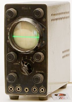
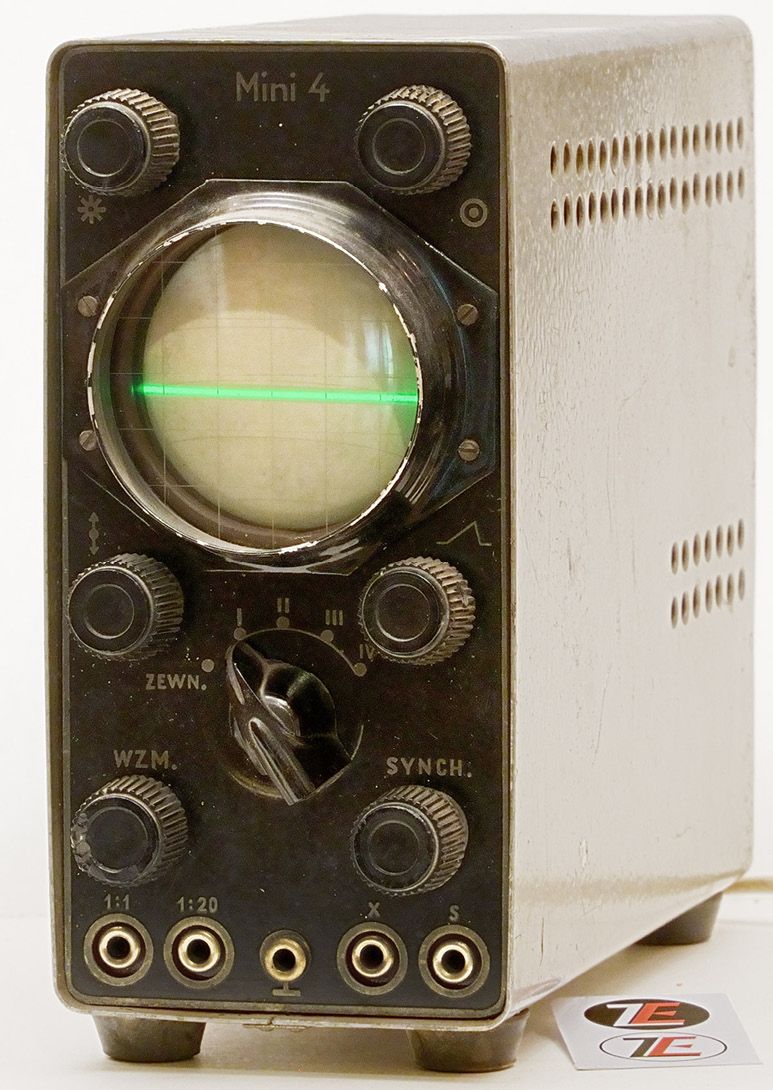
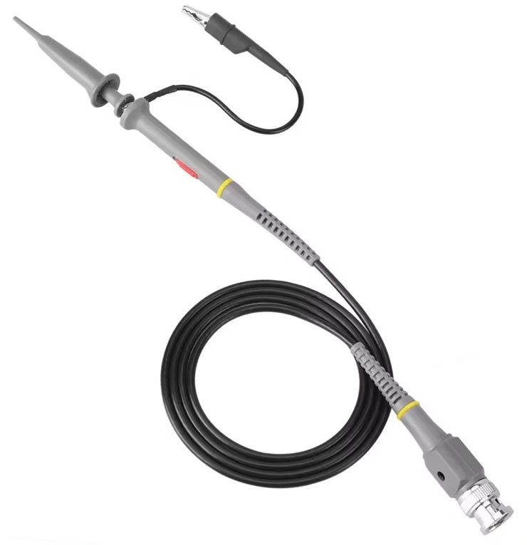
This project enables you to build an adapter for the MINI 4 oscilloscope, allowing it to work with modern oscilloscope probes fitted with BNC connectors:
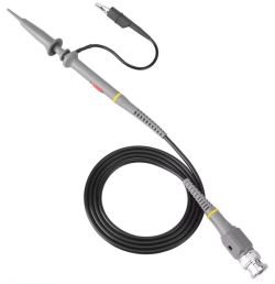
To build it, we will need:
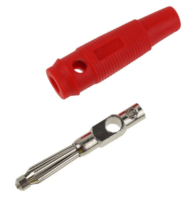
1) Five Amass-type 4 mm banana plugs:
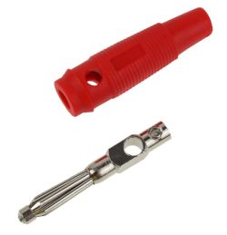
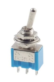
2) Two MTS-102-type two-position switches:
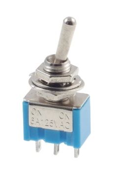
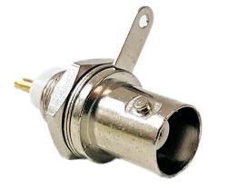
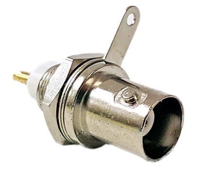
3) Two BNC sockets:
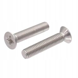
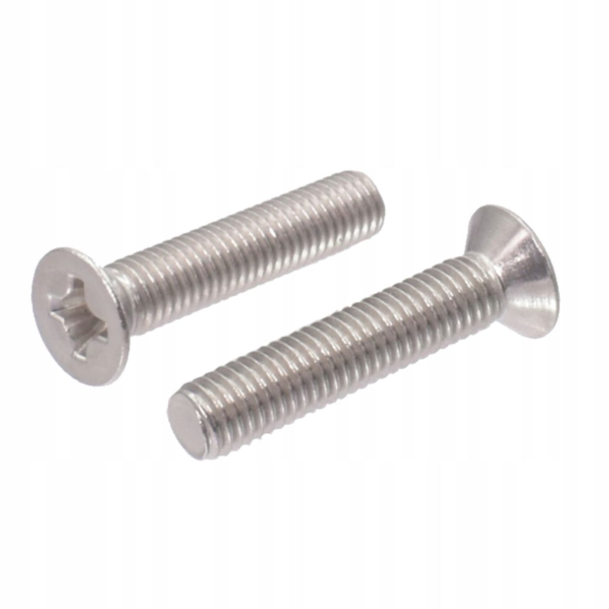
4) Five M3x20 metric taper-head screws:
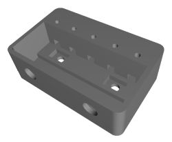
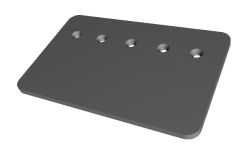
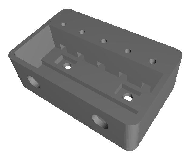
5) A 3D print in two parts:
Files for 3D printing and instructions:
The socket spacing on this oscilloscope is non-standard; it is not the standard 19 mm, but 15 mm and 16 mm. The link above contains not only *.stl and *.g files but also *.ipt files, so that you can adjust the spacing of the banana plugs to suit your specific oscilloscope:

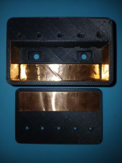
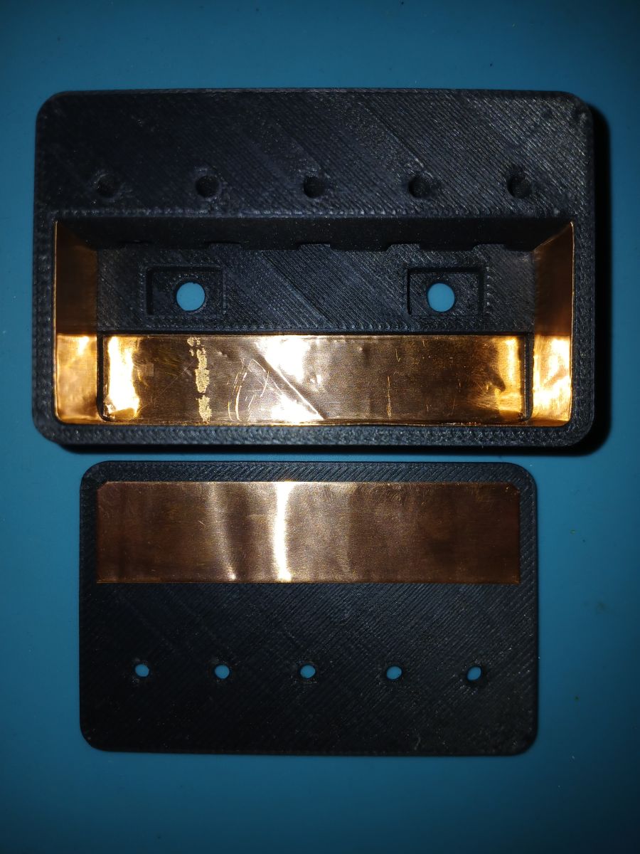
Once the printout is ready, we proceed to line the inside of the casing with copper foil, which will act as a shield:
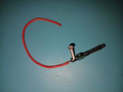
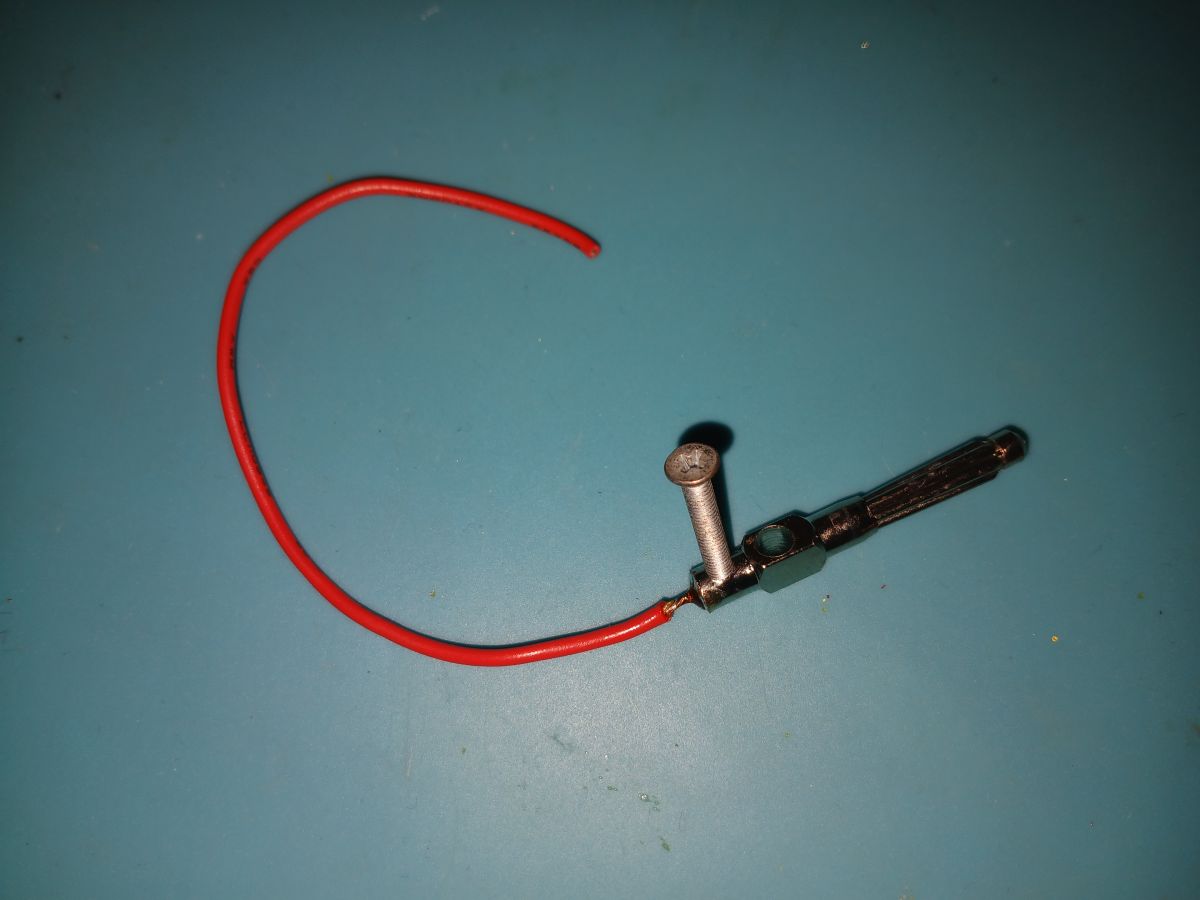
Next, we need to prepare the Amass-type banana plugs by removing the original screws, fitting M3x20 metric tapered-head screws, and soldering the wires directly to the metal component:
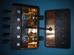
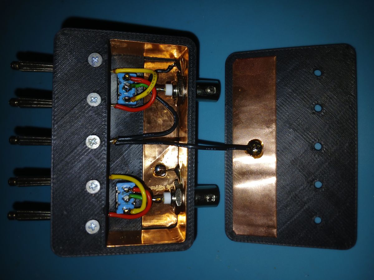
Once the plugs have been prepared, we can proceed with the mechanical assembly of the adapter:
Once the mechanical assembly is complete, we can apply the labelled stickers, which are laminated on one side with transparent adhesive tape and backed with double-sided tape on the other:
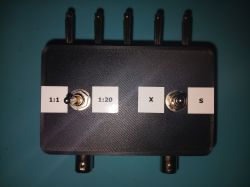
The final step is to lightly tighten the cover using five screws into the threads on the banana plugs. After initially tightening the screws, connect the adapter to the oscilloscope’s banana sockets and then carefully tighten the screws further, taking care not to strip the threads on the banana plugs. The 3D design dimensions include some clearance to allow the spacing of the banana plugs to be adjusted to suit a specific oscilloscope model.
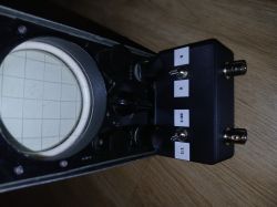
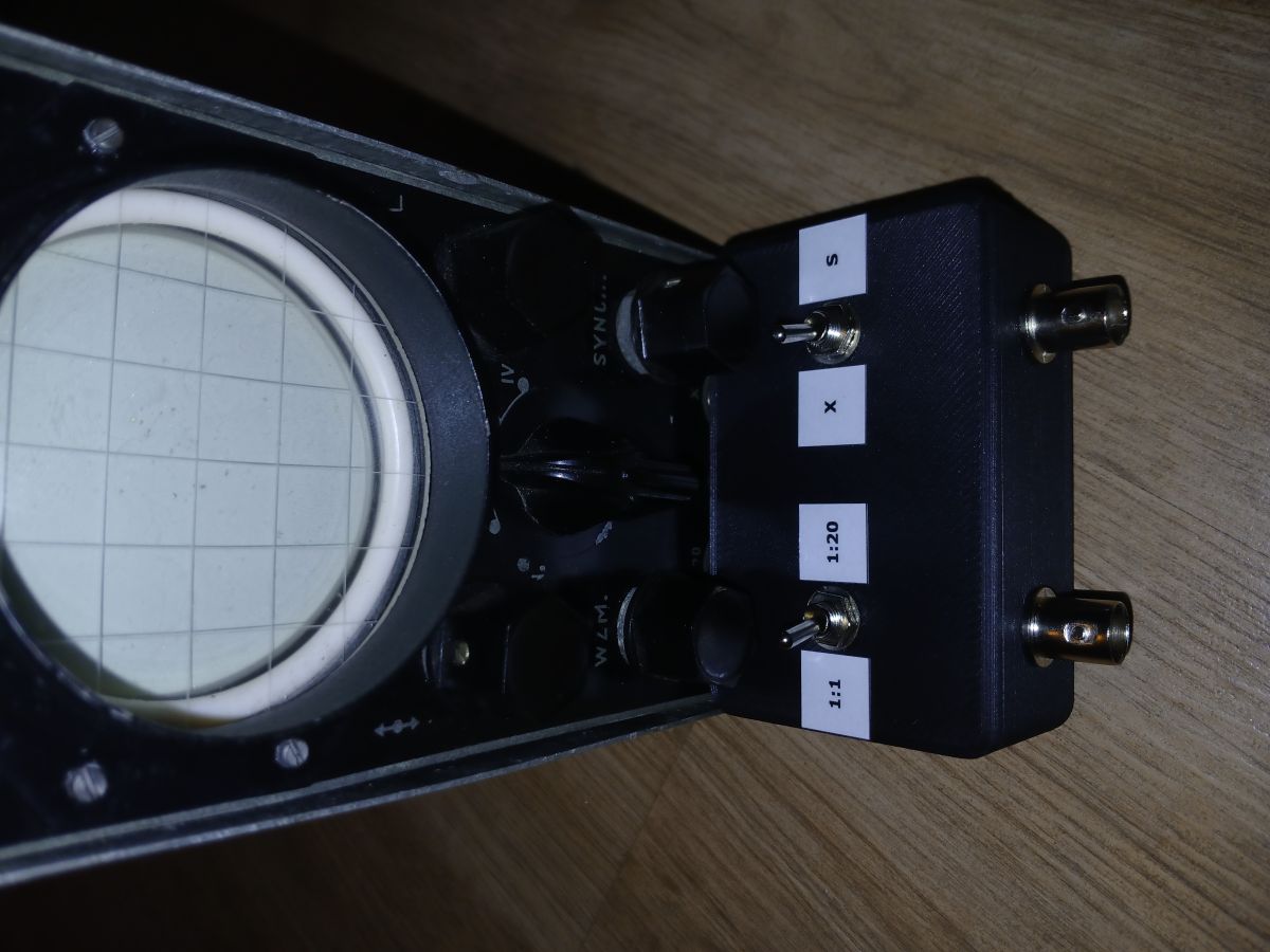
Adapter compatible with the MINI 4 oscilloscope:
Yours faithfully,
Tomasz Łysek
This project enables you to build an adapter for the MINI 4 oscilloscope, allowing it to work with modern oscilloscope probes fitted with BNC connectors:
To build it, we will need:
1) Five Amass-type 4 mm banana plugs:
2) Two MTS-102-type two-position switches:
3) Two BNC sockets:
4) Five M3x20 metric taper-head screws:
5) A 3D print in two parts:

Files for 3D printing and instructions:
The socket spacing on this oscilloscope is non-standard; it is not the standard 19 mm, but 15 mm and 16 mm. The link above contains not only *.stl and *.g files but also *.ipt files, so that you can adjust the spacing of the banana plugs to suit your specific oscilloscope:

Once the printout is ready, we proceed to line the inside of the casing with copper foil, which will act as a shield:
Next, we need to prepare the Amass-type banana plugs by removing the original screws, fitting M3x20 metric tapered-head screws, and soldering the wires directly to the metal component:
Once the plugs have been prepared, we can proceed with the mechanical assembly of the adapter:
Once the mechanical assembly is complete, we can apply the labelled stickers, which are laminated on one side with transparent adhesive tape and backed with double-sided tape on the other:
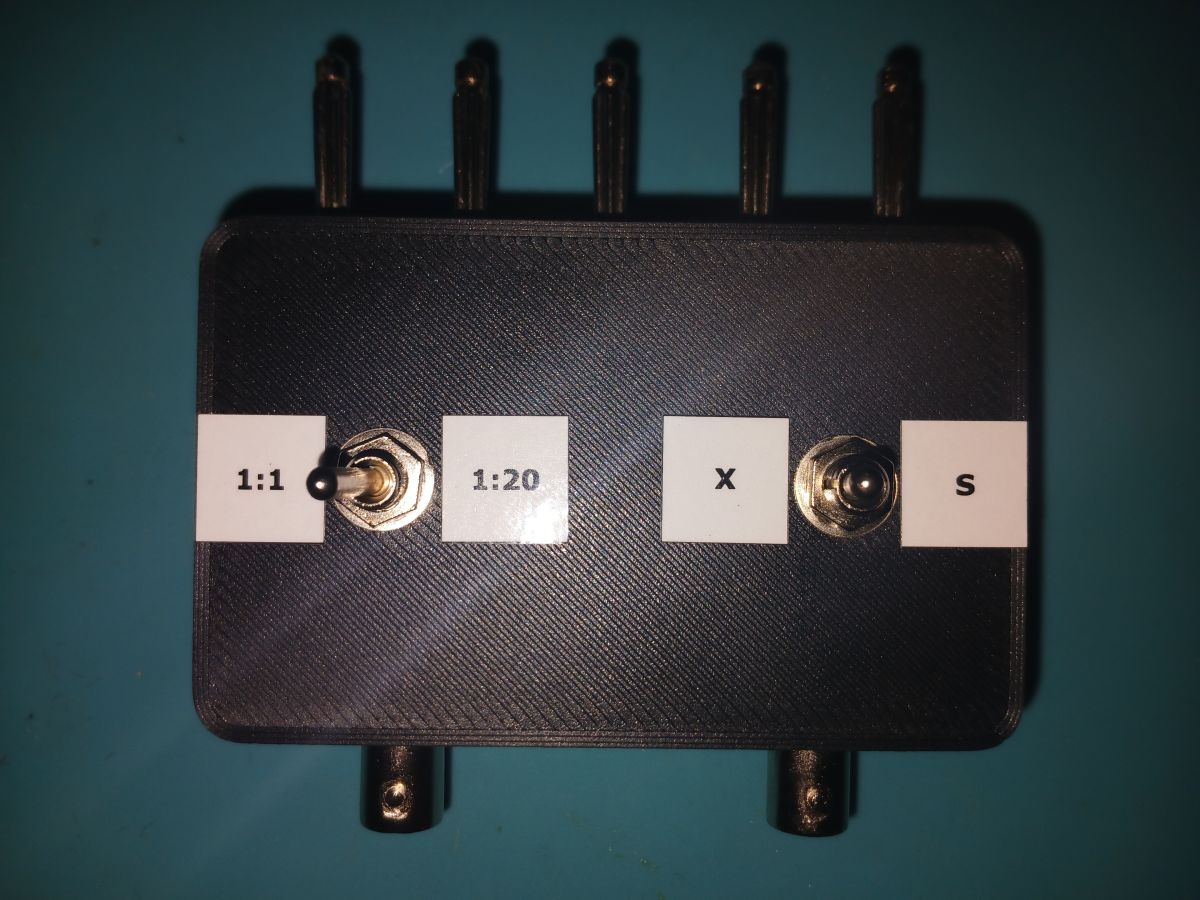
The final step is to lightly tighten the cover using five screws into the threads on the banana plugs. After initially tightening the screws, connect the adapter to the oscilloscope’s banana sockets and then carefully tighten the screws further, taking care not to strip the threads on the banana plugs. The 3D design dimensions include some clearance to allow the spacing of the banana plugs to be adjusted to suit a specific oscilloscope model.
Adapter compatible with the MINI 4 oscilloscope:
Yours faithfully,
Tomasz Łysek
Cool? Ranking DIY

