logo elektroda
logo elektroda
X
logo elektroda

Wiring Surface Reed Switches to Satel Integra 24 System

snayperal 39741 19
ADVERTISEMENT
Treść została przetłumaczona polish » english Zobacz oryginalną wersję tematu
  • #1 2338754
    snayperal
    Level 2  
    As per topic. How many wires are coming out of satel surface reed switches? how to connect to Integra 24?


    ............................................................
    mod:suworow .
    Also worth reading:

    Satel Integra - system installation and configuration - selected issues
    Worth reading also.


    Feel free to check out the rest of the guides, featured topics and articles, on security systems :
    Fixed Security. Alarm systems, Cameras, Intercoms, Gate and roller shutter drives, Home automation. Featured topics and guides. .
    If you do not find an answer to your question in the above topics, please visit the forum
    https://www.elektroda.pl/rtvforum/forum77.html


    I also encourage you to visit the General Guides section where you will find material from the other sections of the forum, including for those starting out in electronics :
    https://www.elektroda.pl/rtvforum/forum510.html .
  • ADVERTISEMENT
  • #2 2338923
    nomad22
    Level 16  
    Hello.
    There are two wires coming out of the reed switch (if they do, because there are some that you unscrew and connect the wires yourself). You need to see what configuration they are in, e.g. 2eol, if so, you simply connect two wires to the control panel terminals and use the software to output the lines as 2eol.
    Regards
  • #3 2338952
    c r i s
    Level 12  
    Just don`t forget to put a 2k2 resistor in series.
  • ADVERTISEMENT
  • #4 2339182
    nomad22
    Level 16  
    Instead of helping, we`ll confuse our friend. :)
    insert a 2.2 k resistor in series if the reed switch does not have any resistors and program the line as parametric.
    Regards
  • #5 2343895
    krz220
    Level 12  
    nonsense and once again nonsense people are gaining points with nonsense statements, above all, the headquarters have the opportunity to nc no eol 2eolnc 2eolno and stop fuck..fuck about some 2.2k resistors, the installer chooses the best option for himself, nc or hgw knows what and no one will stop him from doing so, the system is supposed to be safe. Some statements show that they only dealt with alarms in computer games.
    Moderated By zdzich42:

    Has your friend become too emotional? Temporarily blocks the ability to write

  • #6 2344318
    nomad22
    Level 16  
    Mr. krz220 is an outstanding expert on control panels and in general :)
    And he hadn`t heard about it at all... :)
    And what advice does he give? After your advice, my friend would definitely connect this counter-circuit as needed, especially if it had factory-installed resistors.
    Regards
  • ADVERTISEMENT
  • #7 2345632
    krz220
    Level 12  
    if someone wants to listen to my advice, don`t plug in any 2.2k, you have to do it on 2eolnc, then you can be sure that no one will do anything with the system not armed. I`m not an expert and I won`t let anyone fool me if they want, someone wants to discuss something more advanced. programming of control panels, please contact me at 2.2k, I will not respond
  • #8 2403698
    dijej
    Level 17  
    even I got confused with this connection
    first you need to know what kind of sensor your friend has and then help him
    K-1
    - plastic housing
    - surface mounting - self-adhesive tape, screws
    K-1 2E
    - 1.1k resistors in 2EOL/NC configuration
    - plastic housing
    - surface mounting - self-adhesive tape, screws
    S-1
    - plastic housing
    - surface mounting - self-adhesive tape, screws
    K-2
    - plastic housing
    - recessed installation - without the use of glue or screws
    - once installed, invisible and difficult to locate
    K-2 2E
    - 1.1k resistors in 2EOL/NC configuration
    - plastic housing
    - recessed installation - without the use of glue or screws
    - once installed, invisible and difficult to locate
    S-2
    - plastic housing
    - recessed installation - without the use of glue or screws
    - once installed, invisible and difficult to locate
    Q-3
    - aluminum housing
    - recessed installation - without the use of glue or screws
    - once installed, invisible and difficult to locate
    K-3 2E
    - 1.1k resistors in 2EOL/NC configuration
    - aluminum housing
    - recessed installation - without the use of glue or screws
    - once installed, invisible and difficult to locate
    S-3
    - aluminum housing
    - recessed installation - without the use of glue or screws
    - once installed, invisible and difficult to locate
    S-4
    - plastic housing
    - surface mounting - screws
    - cable connection directly inside the housing
    - double anti-sabotage protection
    - possibility of two-parameter configuration
    I am providing a sensor selection list for the questioner
  • #9 3781068
    milek99
    Level 15  
    Hello
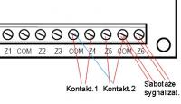
    I have a problem with connecting Satel S4 reed switches.
    I connected them as in the attached drawing, but on the CA-6 KLED-S keypad they flash every 2 seconds. diodes from these inputs. This probably means sabotage.
    What did I do wrong??
    The connection diagram is from the Reed Switch manual

    Please give me a quick tip :|
  • #10 3781358
    Anonymous
    Level 1  
  • #11 3781702
    milek99
    Level 15  
    In my hurry, I forgot to attach the drawing :D
    Maybe if you see the drawing, you will tell me whether it is connected OK and how it should be programmed in the control panel.
    I will add that I can program it as: NC, NO, EOL, 2EOL/NC, 2EOL/NO.
    I have it set as 2EOL/NC.
    And I`m not opening a new topic because this one was not closed and corresponds perfectly to my problem.
  • #12 3781843
    Anonymous
    Level 1  
  • #13 3785213
    milek99
    Level 15  
    I solved the problem.
    I checked the resistances and everything was OK, but I still had a sabotage on reed switch 2.
    First, I had it connected as in the attached diagram (red), on reed switch 2.
    After thinking about it, I connected reed switch 2 to another COM (blue in the attached diagram).
    From that moment everything started working.
    I will add that I installed the alarm for the first time and now everything works fine :) but I would still like to find out why the red connection was sabotaged :|
    Thank you very much sharp for very quick and specific help.
  • #14 3785339
    adamjur1
    Level 41  
    And how are your siren sabotages connected - in parallel?
    This is not smart because it does not protect these elements.
    If changing the ground of the inputs changed the operation of the control panel, this indicates damage to the comma, which is rather difficult and unusual......
    Regards, J
  • #15 3785432
    Anonymous
    Level 1  
  • #16 3785541
    milek99
    Level 15  
    In fact, in parallel, I will change it to serial, and as for the COM, the tamper of the external and internal siren is connected to it and it works without any problems, but when I connect the COM connector from the reed switch to this connector, I still have tamper.
    I have the tamper input type set to "Enclosure", but this applies to inputs, not COMs.
  • #17 20397312
    plucinskil
    Level 2  
    Hello,
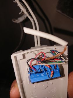
    How to connect the BL-4 satellite reed switch in series with the Bosch PIR detector? In the photo below, the PIR sensor is connected and the cable is led out under the reed switch
    l Wiring Surface Reed Switches to Satel Integra 24 System
  • #18 20397331
    bhtom
    Level 38  
    Hello,

    In series with the detector`s alarm contact. But why such tinkering? Isn`t there a separate line available at the headquarters to do this properly?

    Regards.
  • ADVERTISEMENT
  • #19 20397341
    plucinskil
    Level 2  
    This is how the installer connected the detector and led a white 6-wire cable from it to connect the gate reed switch. The reed switch has only 2 wires, so I ask which contact should I connect them to?
  • #20 20397354
    bhtom
    Level 38  
    Hello,

    First, check whether you have free lines in the control panel; if so, connect the wires of the reed switch to the free wires of the detector cable, which probably goes to the control panel.

    Regards.

Topic summary

The discussion revolves around wiring surface reed switches to the Satel Integra 24 alarm system. Users clarify that surface reed switches typically have two wires, although some may require user-connection. The configuration of the switches, such as 2EOL (two end-of-line) or NC (normally closed), is crucial for proper connection to the control panel. It is recommended to use a 2.2k resistor in series if the reed switch lacks built-in resistors. Several users share troubleshooting tips for issues like tamper alerts and connection problems, emphasizing the importance of correct wiring and programming settings in the control panel. Additionally, there are inquiries about integrating reed switches with other devices, such as PIR detectors, and ensuring proper line connections.
Summary generated by the language model.
ADVERTISEMENT