FAQ
TL;DR: 95 % of Bosch alternator failures are traced to the voltage regulator [Elektroda, decybel91, post #9933569]; "You do not need a diagram" [Elektroda, grzesiek08, post #3237429] With a 12 V battery, 21 W lamp and ~1 800 rpm drill you can confirm charge on the bench.
Why it matters: A 10-minute bench test saves hours of reinstalling a dead unit and helps pinpoint whether you need brushes, a regulator or a full rebuild.
Quick Facts
• Cut-in speed for most 12 V alternators: 1 500–2 000 rpm rotor (≈3 000–4 000 rpm engine) [Bosch Training, 2018]
• Test lamp spec: 12 V, 21 W single-filament bulb (e.g., P21W) [Elektroda, grzesiek08, post #3237429]
• Typical regulator price: €30–€180 depending on brand and pin-count [Autodoc Price List, 2023]
• 3-pin Denso layout: IG + (ignition), L (warning lamp), S (battery sense) [Elektroda, carrot, post #19608638]
• Diode bridge sold as a complete pack; individual diodes rarely stocked [Elektroda, carrot, post #9932144]
How do I bench-test a standard alternator with three terminals?
- Clamp the case in a vice and connect B+ to battery positive, case to negative.
- Insert a 12 V/21 W bulb between battery + and the small ‘L’ lamp terminal.
- Spin the pulley at ≈1 800 rpm with a drill. The lamp should go out and voltage rise above 13.8 V. If the bulb stays lit, check diodes or regulator [Elektroda, grzesiek08, post #3237429]
What rpm do I need to reach for the alternator to excite on the bench?
Most 12 V units start charging once rotor speed exceeds 1 500–2 000 rpm, roughly 25–30 Hz stator frequency [Bosch Training, 2018]. A handheld drill on high gear usually meets this. Below cut-in, the bulb stays lit and voltage stays at battery level.
Can I test an alternator without using a power drill?
Yes, a small engine or lathe can spin the pulley. You must still hit cut-in speed. Turning by hand will only check bearings, not output [Elektroda, macvir, post #9334915] "Wake him up" with proper rpm first [Elektroda, macvir, post #9338167]
How is the battery warning lamp wired during a bench test?
Wire one side of the 21 W lamp to battery positive, the other to the lamp (L) terminal. When the alternator’s internal regulator energises, L rises to B+, eliminating current and the lamp goes dark [Elektroda, grzesiek08, post #3237429]
I have a 5-pin, computer-controlled alternator. Can I still bench-test it?
Yes, but you need a programmable field controller or manufacturer schematic. Without LIN/BSSM commands, the regulator may stay at minimal field. Basic lamp-and-battery tests only show bearing or diode faults, not regulation quality [Elektroda, daniel, post #4462104]
Which part fails more often: regulator or diode bridge?
Forum data show regulators account for 95 % of Bosch-type failures [Elektroda, decybel91, post #9933569] Diodes rank second; brushes and slip-rings follow. Still, replace the full diode pack because single diodes are hard to source [Elektroda, carrot, post #9932144]
How can I tell if an alternator diode is shorted or open?
Using the diode test mode, a healthy diode drops 0.3–0.6 V forward and infinity reverse. A short shows 0 V both ways; an open shows infinity both ways. In Astra CDTi units, technicians saw two open diodes in one bridge [Elektroda, Anonymous, post #9930048]
What causes brushes to hang and stop charging?
Oil or diesel seepage mixes with carbon dust, forming sludge that jams the brush holders. When it dries, springs can’t push the brushes, leaving half their length unused [Elektroda, carrot, #9340636; miler80, #9341506]. Edge case: after pump repair, charging fails because the sludge hardens within hours.
Why does my charge lamp stay on after I changed brushes?
Brush replacement fixes mechanical contact but not electrical faults. A weak regulator, open stator phase or shorted diode will still pull L low, keeping the lamp lit even with new brushes [Elektroda, 9933009–9933038].
Are alternator diodes more likely to short or go open-circuit?
Both happen. Some techs report more shorts [Elektroda, robert7319, post #9930044]; others find open diodes in Ford and Opel units [Elektroda, Anonymous, post #9930048] Heat spikes favour shorts, reverse-battery events favour opens. Either way, replace the full bridge.
Quick 3-step how-to: Replace a bolt-on regulator
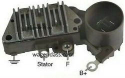
- Remove two Phillips screws and slide out the old regulator-brush pack.
- Blow out carbon dust; inspect slip-rings for grooves.
- Install the new pack, torque screws to 1 Nm, and re-test on the bench.


