logo elektroda
logo elektroda
X
logo elektroda

Connecting and Replacing Old Intercom with New Urmet 1131: Wire Colour Guide

kurnajanek 56815 28
ADVERTISEMENT
Treść została przetłumaczona polish » english Zobacz oryginalną wersję tematu
  • #1 3522852
    kurnajanek
    Level 10  
    Hello :) I'm desperate and I don't know much about electronics!
    I have an intercom that is in agony, more tape and glue on it than possible :) the decision was made to replace this device :) (wife :) It wouldn't be a problem if I knew how to do it :) !!

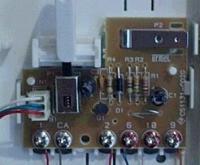
    In the old intercom, the wires are soldered to the board, there are 6 of them, the new (almost) Urmet 1131 intercom, as far as I remember, has 5 places to connect the wires. Can you tell me what color of the cable I should connect to which contact of the new intercom to make everything work :)
    photo 1 shows my old intercom
    photo 2 new but this is a photo from the forum from you and there I see 6 places to connect I think there are 5 :)

    1 Connecting and Replacing Old Intercom with New Urmet 1131: Wire Colour Guide


    2 Connecting and Replacing Old Intercom with New Urmet 1131: Wire Colour Guide

    in total, in photo No. 2 you can see the colors of the cables, but you can see two red ones there :( and I don't have two, maybe it's a bridge? , secondly, it seems to me that there are 5 places for screwing the cables :) and in photo 6 I do not know if there are different types of intercoms with 6 and five connection points!!??

    Please help, my wife has premenstrual syndrome, you know what that means :D
  • ADVERTISEMENT
  • Helpful post
    #2 3523579
    Robert 1960

    Level 32  
    Hello !
    There may also be 6 wires in the Urmet uniphone, but you can't see much in the picture of the old uniphone, take a picture of the whole thing so that you can see where these wires go, you can suggest something!
    Regards !
    Robert
  • ADVERTISEMENT
  • #3 3523622
    zybex
    Helpful for users
    I've never installed these, though
    CA - is a call
    1 - handset (SU)
    2 - microphone (MU)
    6 - mass (0)
    9 and 10 opening button

    The picture shows a broken bridge. This must be the case with a six-wire system.
    For starters, set these two to the open button. Save these colors. Then (if you have a meter) you'll be fine.
  • #4 3524115
    kurnajanek
    Level 10  
    well :) thanks for showing interest :) The day is coming to an end, I'm burnt out ;)
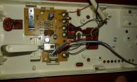
    I'm attaching a photo of the model I'm about to wear:
    Connecting and Replacing Old Intercom with New Urmet 1131: Wire Colour Guide


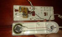
    , as I said, I have five places to which the wires can be connected, not 6 as in the previous photo (moreover from the forum) and now the second one that is to be replaced :) : ( Someone asked for more :)

    Connecting and Replacing Old Intercom with New Urmet 1131: Wire Colour Guide ]

    someone wrote to me:

    2 - mass 9-something else etc ..... can you, if it is predetermined, speak in colors ?? :) because I don't really know how to determine which mass has which functions
  • ADVERTISEMENT
  • #5 3524146
    Robert 1960

    Level 32  
    Hello !
    You have 5 because you don't have a screw from 1, you either fell out or it wasn't there and it should have been!
    Your photos still don't show the microphone or the speaker, so you don't know where these wires go!
    Regards !
    Robert
  • #6 3524262
    kurnajanek
    Level 10  
    should I take a picture of an unfolded handset, an old intercom????
  • Helpful post
    #7 3525261
    martelek
    Level 13  
    If you don't have a meter, disassemble the handset and see which wires from the twisted cable are connected where. There will most likely be 3 wires coming out of the handset, where the one that connects one contact of the microphone and the loudspeaker in the handset is the ground that should be connected to terminal 6 from the new uniphone. The wire that is connected to the second contact from the speaker of the handset should be connected to terminal 1 (where you do not have a screw) and the wire from the microphone to terminal 2. To determine which wires are responsible for opening the electric strike, unscrew this plate in the old uniphone and see which wires this opening "plate" shorts and connect them to terminals 10 and 9 and you will have the last "call" wire that needs to be connected to the CA terminal
  • ADVERTISEMENT
  • #8 3535019
    kurnajanek
    Level 10  
    welcome back ! So I did as you advised me :) the intercom works almost flawlessly :( but it almost makes a big difference :) ........ you can't hear me downstairs, the silence is like sowing poppy seeds, the rest of the functions are ok :)
    please advice :)
  • #9 3535895
    zybex
    Helpful for users
    The second clamp is the microphone. You must have a DC voltage (plus) in the range of 8-15V (relative to the ground cable) on the cable you connect here.
  • #10 7301839
    /matthew/
    Level 11  
    And I have a question.. I would like to add the ability to turn off the ringing signal, so I thought I would add some ordinary switch (because probably such a solution is correct), and now should I connect this switch to 1, i.e. the loudspeaker lines or to the CA-call? Yes, I have it all connected:
    Connecting and Replacing Old Intercom with New Urmet 1131: Wire Colour Guide
  • #11 7302167
    Nowart
    Level 20  
    The easiest way is to put a regular switch under the call line, i.e. CA. I wonder what the potentiometer on the handset is for, but that's another story.
    Regards
  • #12 7302265
    /matthew/
    Level 11  
    Thanks for the answer. And the potentiometer is probably a remnant of an earlier intercom :)
  • #13 7303152
    zybex
    Helpful for users
    In series from the circuit breaker (or potentiometer) call line to the CA. The second potentiometer is probably the volume. Maybe with the new one it will be redundant.
  • #14 7305313
    Dariusz Lewtak
    Level 12  
    I don't know what power supply you have, if it is 18N or 19 ... then the volume and call volume control is in the power supply. You definitely need to disconnect the perk from 1.
  • #15 7305701
    zybex
    Helpful for users
    Dariusz Lewtak wrote:
    I don't know what power supply you have, if it is 18N or 19 ... then the volume and call volume control is in the power supply. You definitely need to disconnect the perk from 1.

    I am also for the elimination of this potentiometer. Sometimes I put a resistor (470-1500Ω ;) into the line of microphones, but only if there is feedback when picking up the handset.
  • #16 8077894
    bartoszmail
    Level 11  
    Hello, I won't create a new topic, so I'll ask here.

    I have an F&M WRD 6i intercom power supply, I can't find a diagram for this, can anyone decipher this power supply?
    The installation is with an electric lock,
    And there is one more question, is it possible to connect a total of 3 uniphones to this power supply, to a 3-button intercom, everything is URMET, uniphones as in the subject.
    I will add that here, where there are the most wires, there is '' - ''
    Connecting and Replacing Old Intercom with New Urmet 1131: Wire Colour Guide
  • #17 8078632
    zybex
    Helpful for users
    The number of uniphones is arbitrary. It depends only on the cassettes, i.e. how many buttons it has, so many independent uniphones can be connected.
    Download the manual from the WRD-45i, for example, because the markings are the same.
    http://www.fimpro.com.pl/pobierz.php
  • #18 8079766
    Nowart
    Level 20  
    I support the previous speaker because if the number of call buttons is equal to the number of uniphones, then it is ok. In the case of 1 call button, I would not exceed the number of 3 pieces due to the load on the generator line.
  • #19 8081081
    bartoszmail
    Level 11  
    in the cassette of the intercom I have a diagram, and zaicski :| 12v, 0v|, |GL, GL|, |MK, 441|, G1,2,3, G, to which one should the generator signal be connected?
  • #20 8081492
    zybex
    Helpful for users
    Logically, the generator input will be G and the generator outputs to the subscribers will be G1, G2, G3.

    Anyway, here's a piece of the installation diagram.
    Connecting and Replacing Old Intercom with New Urmet 1131: Wire Colour Guide
  • #21 8091476
    bartoszmail
    Level 11  
    It helped me a lot, thanks for your help!
  • #22 8107326
    LukasSandyra
    Level 12  
    Hello, I'm just replacing the intercom with 1131, I connected everything and it seems to be fine, but the problem is that I can't connect the microphone because then the speaker at the bottom goes crazy and you can hear a squeak, I mean I think so because I only heard it through the loudspeaker in the intercom handset, and when I call it is almost inaudible, what to do then?? I should add that I live in an apartment.
  • #23 8616984
    Juniorkrze
    Level 2  
    Hello
    Buddy, try to load the microphone lines (MU) in the camera with some resistor, e.g. 11k, because you have a new camera and you may have feedback.
  • #24 8893483
    lakim
    Level 12  
    Hello,

    I have the same intercom. Unfortunately, this is a truncated version and there is no volume down. Please advise where to insert and what potentiometer to enrich it with this option?

    Regards,
  • #25 8895156
    zybex
    Helpful for users
    Put the resistor on the microphone terminal. If we don't know what the value should be, we try different ones. Most often it is supposed to be a resistor in the range of 1 kΩ. Of course, you can give a small potentiometer as a resistor (if you want).
  • #26 8895259
    LukasSandyra
    Level 12  
    But you probably described the method of how to turn down the microphone to hear it less at the gate and I had to do it, because if it wasn't for the potentiometer, I would only have a squeak at the gate. But if a colleague meant, for example, to lower the voice in the handset speaker, then the potentiometer should probably be on the speaker terminal, while when it comes to lowering the call, it should be on the call terminal. At least I think so.
  • #27 14789582
    zielony:(
    Level 2  
    Hello
    I have an intercom urmet 1131 connection as in the attached photos
    handset green red cable
    blue and white microphone
    while camera 1-dark brown, CA-light brown, 2-green, 6-blue, 10-empty, 9-red
    The problem is that no one can hear us downstairs. We hear them and can open the door. Is there an error in the installation in the building or is the connection wrong Connecting and Replacing Old Intercom with New Urmet 1131: Wire Colour Guide Connecting and Replacing Old Intercom with New Urmet 1131: Wire Colour Guide
  • #28 17653568
    elkubaso
    Level 13  
    I replaced the old GM-WO handset with the Urmet 1311. Everything works except the microphone in the handset (you can't hear "Who's there?" with the cassette). In GM-WO it has only a diode on the board, and in Urmet there are already several capacitors and resistors. Can you tell me what is the cause of this and how to solve this problem :?:
  • #29 17653946
    zybex
    Helpful for users
    The new one has some elements that the old one didn't have, but don't worry about that. In the old one, these elements were probably in the microphone itself (microphone amplifier), because it used to be done anyway. Regarding the connection itself, you did not provide a list of the old uniphone, so how can I help you?

Topic summary

The discussion revolves around replacing an old intercom with a new Urmet 1131 model. The user seeks guidance on connecting six wires from the old intercom to five terminals on the new unit. Various responses suggest identifying wire functions, including call, microphone, and mass connections. Users recommend using a multimeter to trace wire connections and provide color coding for proper installation. Issues with microphone functionality and feedback are also addressed, with suggestions to use resistors to mitigate problems. Additional inquiries about integrating switches and potentiometers for volume control are discussed, emphasizing the importance of correct wiring for optimal performance.
Summary generated by the language model.
ADVERTISEMENT