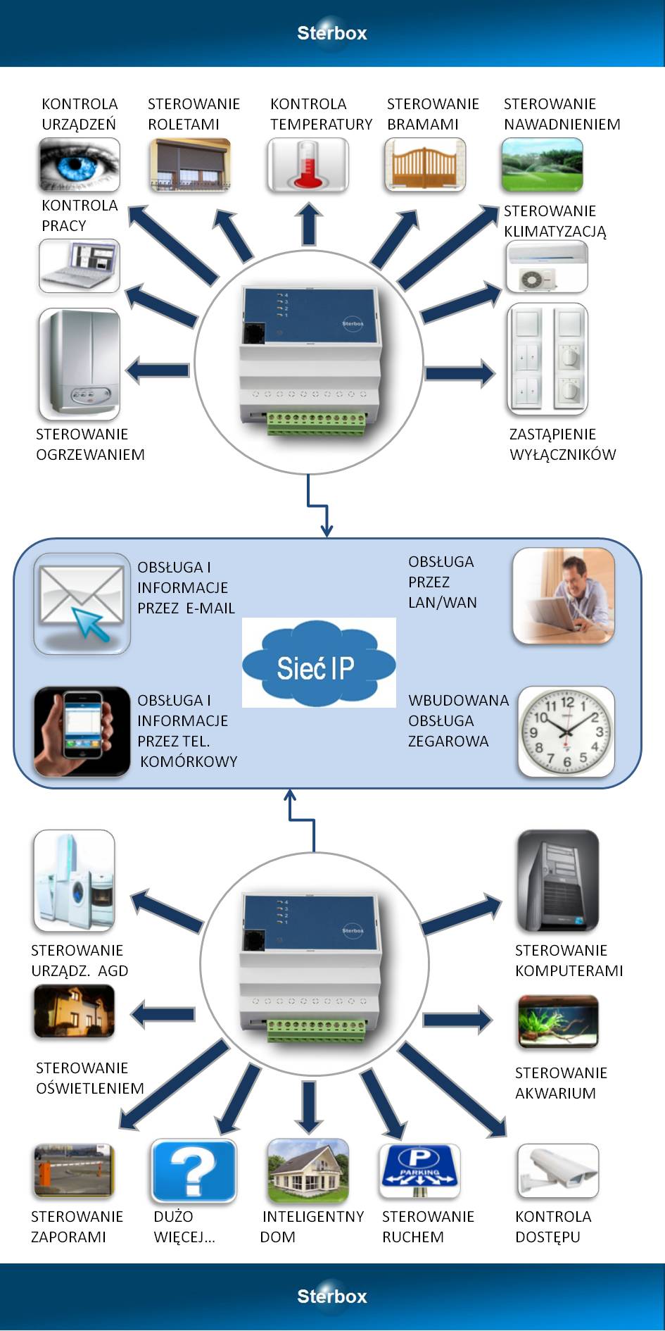
I’d like to share with you my experiences with what’s known as a ‘smart building’ (SB).
Six years ago, when I was building my house, people were only just starting to talk about smart homes. At a trade fair, I saw a German company with a system that was shockingly expensive (prices started at 20tys zł for installation). I wanted a house like that, but not at that price...!
That’s why I decided to come up with my own solution. The most important factors were cost and functionality. I call it a ‘semi-smart home’

As I worked it out, the cost came to about 3,000 zł on top of the costs of the ‘standard’ electrical, alarm, aerial, telephone and Ethernet installation, which I would have had to fit anyway.
I started by laying the cables before the floors were screeded and the walls were plastered. The system is centralised (2-star topology), meaning that on the ground floor, in addition to the alarm control panel and the alarm distribution box, there is a 56-pole electrical distribution box. As usual, all the wires from the IR detectors and reed switch detectors on all the doors and windows throughout the house, plus the siren, converge at the alarm control panel. From the electrical box, all the 230V AC power supply cables branch out (to each load separately! as the relays are in the boxes) along with all the 24V DC control cables. The control cables consist of an Ethernet cable. On the upper floor, there is the second element of the star topology: a second 56-pin electrical box (which has reduced the need to run a large number of cables between floors). Several control and power cables are laid between the boxes to provide power between floors and transmit signals between floors, etc. In every room, in addition to standard lighting and sockets, there are ‘controlled sockets’. This allows, for example, a floor lamp to be connected and switched on using a switch by the door, or switched off when the occupants leave the room (e.g. by activating the alarm). Of course, the cables for the alarm sensors and the telephone also include an Ethernet cable for the antenna – as standard. To minimise the amount of wall chiselling, the cables are routed through a layer of polystyrene beneath the screed or above the suspended ceiling.
Alarm.
The Satel CA64 control panel (the Integra wasn’t available at the time). It naturally performs basic alarm functions and sends voice messages to household members’ mobile phones in the event of an incident. It also allows you to call the house from outside and control the system using your mobile phone keypad (e.g. I can remotely switch on the garden sprinkler system when we’re away from home for a few days, etc.). In addition, it provides:
- mobile phone notifications: regarding a power cut lasting over 1 hour, critical battery status, other faults, tampering, alarms from the CA64 and flooding in the boiler room (the ‘F&F PZ828’ flood sensor connected to one of the CA64’s inputs), and doorbell rings (e.g. the postman).
- Switching off all interior lighting and controlled sockets when the alarm is armed (the CA64 controls the ‘switch everything off’ circuit in the fuse box) – e.g. to prevent a fire caused by a forgotten iron.
- Switching on the light in the hall and outside the front door (outside the front door for 2 minutes only) when entering the house after dark whilst the CA64 is armed (front door reed switch + signal from the ‘F&F AZ112’ twilight sensor)
- Switching on the light only outside the front door for 2 minutes when the door is opened after dark and the CA64 is not armed (i.e. a household member is walking around the property after dark)
- Shut off the water supply throughout the house when the CA64 is armed and turn it back on when it is disarmed (electric valve controlled by the CA64).
- Switch on the hot water circulation for 3 minutes after the CA64 is disarmed so that there is hot water at the taps immediately upon entering the house.
- The doorbell button at the gate and front door activates the buzzer and, whilst the system is armed, logs the event to the CA64’s memory and sends a notification to your mobile phone that someone is ringing the doorbell (via a voice message), it powers on a 12V camera (a car security camera bought on Allegro for 150 zł, which records what is happening outside the house onto an SD card; it can also activate automatically – it detects movement and has IR LEDs). Recording works on a ‘first-in, first-out’ basis. A 2GB SD card is sufficient for 0.5 hours of recording. An 8GB card lasts for 4 hours. You can access the footage remotely via the internet – you can connect it, for example, to a NetiaSpot modem or a PC – it is recognised as a USB drive)
- the doorbell button only activates the buzzer when the alarm is disarmed, i.e. when someone is at home.
Buttons for switching on lights, etc.:
The buttons are double monostable switches, used for roller blinds. The cable to the button box is an Ethernet cable (the cheapest option, as the voltage here is a safe 24V DC). Up to 3 double buttons can therefore be connected to a single cable (leaving one wire spare). A single circuit (e.g. a lamp) can be controlled by several buttons located in different parts of the room or even on a different floor – you simply need to connect them in parallel. Each button works in a similar way to a traditional ‘two-way switch’ – it switches the load on and off.
The buttons have the following functions:
- pressing once switches on a single circuit (e.g. ceiling lights or controlled sockets in the room) (F&F BIS411)
- pressing a second time switches off that circuit (this is how the BIS411 works)
- holding down a button for 2 seconds switches off the entire room (I call this a ‘section’), including controlled sockets and lighting. When leaving the room, simply hold down any of the buttons to switch off all the lights in the room you are leaving. There is no need to press different buttons several times.
- Some models have more extensive functions (BIS414). The first press switches on, for example, the ceiling light; the second switches off the ceiling light but switches on the sockets; the third: both the ceiling light and the sockets are on; the fourth switches off both the ceiling light and the sockets. This is the standard operation of the BIS414.
- Holding down for 2 seconds, as above, switches off the room
The above functions are implemented by the BIS411 and BIS414. Two additional components, the PCR512 and PCR513, detect a 2-second press-and-hold in each circuit and, using one PK-2K per section, switch off the relevant section. Sections may overlap. The scope of each section is set by connecting standard 1N diodes as appropriate. For example, pressing one of the buttons (by the front door) for 2 seconds switches off all sections in the house and garage, except for the outdoor lighting. This is useful when you want to go out without arming the alarm and switch off all circuits (arming the alarm automatically switches everything off after the exit delay).
Whilst carrying out this installation, I rang F&F (in Pabianice, I think) and asked if they made components with separate inputs for setting and resetting the status. It would have been easier to achieve the desired effect and add even more features. They replied at the time that they had no such plans. Two years later, they launched the BIS412. I suppose they liked my idea.
Lighting control is handled by both 56-pole distribution boxes. They contain standard fuses, a main switch and a residual current device. In addition, the F&F components (24-volt) handle all the lighting control on the floor:
- switching on outdoor lighting after dark and switching it off when it gets light (house number, LED garden lighting, etc.). Switching off the outdoor lighting at dawn also works if the lighting has been switched on manually by a resident and the automatic switch-on function was not activated – this is handled by the CA64.
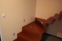
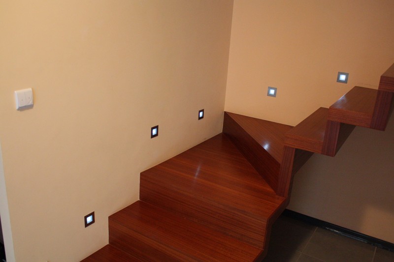
- Switching the LED lighting on the internal staircase on/off. They stay on all night. The staircase LEDs are wired to provide as much light as possible whilst using the least amount of power. Each light has three brightness settings (4, 12, 16 LEDs). The controller only operates the first setting – the most energy-efficient one. It would also be possible to switch them off completely when no one is at home at night (CA64). However, I’ve calculated that the first brightness level of my 10 staircase LED lights consumes less than 1 zł per month (they’re on every night from dusk till dawn) (0.2W each, totalling 2W, which is 0.5kWh per month). Just to emphasise once more: the lights are my own series-parallel design with selected resistors, without a stabiliser. Factory-made LED lights with a built-in stabiliser each consume around 2W! and do not allow individual LEDs to be switched on or off.
Ethernet network
– connects home computers and also allows the use of a NAS (LaCie 1TB) with DLNA support – we watch films from the drive directly on the TV. The drive is visible on the network to both computers and the TV. At the moment, I have a second DLNA server on the network because I’ve connected a Netia Spot modem to the network, which also has this function.
Telephone and aerial network
It is essentially not used, as the cordless telephone I’ve installed, with two handsets, has coverage throughout the house. The base unit is located near the incoming telephone cable. The second base unit requires no cable, only a power supply, and is situated upstairs. Cable TV – cable is only routed to two rooms – where the TVs are located. This allowed us to save on cabling.
Heating
Underfloor heating on the ground floor and in the bathrooms. Radiators in the bedrooms. Controlled by a weekly thermostat. The thermostat can be moved to any room (connected to an unused telephone line) – this allows the heating to be adjusted for a specific room or to switch off heating in rooms that are not in use. Switching off the underfloor heating in the living room does not switch off the underfloor heating in the bathrooms. The radiators upstairs operate at high efficiency, which means they are smaller. It took me two months to fine-tune the balance between the underfloor heating on the ground floor and the rest of the house, which is heated by radiators. The aim was to ensure a similar temperature throughout the house with just a single control thermostat. I could also add a feature to lower the temperature when nobody is at home (CA64). I’ll leave that for later.
Additionally:
- DHW circulation – to minimise heat loss, I used a separate weekly thermostat to programme the DHW draw-off times for the appropriate hours in the morning and evening. To prevent the pump from running constantly – the thermostat’s temperature sensor is attached to the hot water return pipe, and when it detects heat in the return flow (set to 30°C) (i.e. there is already hot water in the pipes), it switches off the DHW circulation pump. When the water cools down at the sensor, it switches the pump back on. This happens at the programmed times in the morning and evening, with different schedules for weekdays and weekends. It would also be possible to add a feature to start the circulation for, say, 2 minutes, when the CA64 (the existing IR sensor in the bathroom) detects a household member’s presence in the bathroom at a time other than the programmed hours.
UPS circuit
There is one UPS and dedicated wiring. The UPS sockets are colour-coded so that a vacuum cleaner isn’t accidentally plugged into them. In total, the wiring has been run to three rooms. Initially, it also protected the power supply to the CA64 and the 24VDC system. However, this proved unnecessary. It now powers only the PCs.
Phase loss
I also had a circuit breaker that switches phases in the event of a phase loss affecting the power supply to the UPS, as well as one lighting circuit in each room.. However, this F&F design was a complete failure. Switching too quickly burnt out the contacts; they would stick together and go ‘boom’. I gave up on it ages ago.
Estimated costs (in addition to the standard electrical installation, which would have had to be done anyway):
- Ethernet cable: 2 reels of 100 m each. 200 zł (computer network, telephone network, control network)
- 230V cable – 100m. 300 zł (a separate cable from the junction box to each load)
- Aerial cable 50 zł, speaker cable – 100 zł
- F&F electronic components (24VDC): depending on the scope of the installation, 50 units, costing around 1,800 zł, plus a 24VDC switching power supply for a busbar or a cheaper alternative.
- Plastic conduits, etc.: around 300 zł
- Labour/concept – DIY: 0 zł
What’s next
In the future, I plan to change the control system in the electrical cupboard. Something with a cheap touchscreen (e.g. GPS with WinCE) instead of buttons. We’ll see.
Cheaper heating would also be useful (I have gas), but it’s unlikely to work – the dense development, close neighbours and small plot rule out wind and a heat pump. The climate isn’t conducive to solar power. Perhaps an ‘ice pick’ system or inverter air conditioning. I’ve got almost everything wired up for heat recovery.
In the pictures:
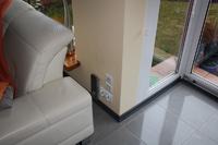
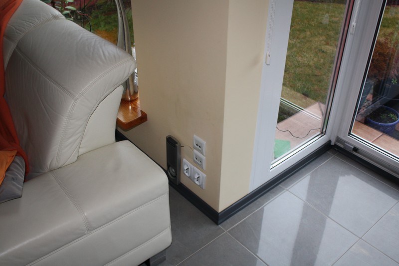
There are two sockets because the left one is ‘controlled’ and the right one is ‘permanently powered’. This means I can switch on the floor lamp using the switch on the wall by the entrance.
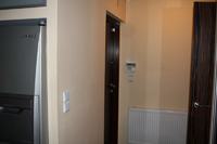
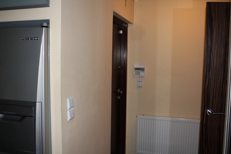
The entrance to the house. The top switches control the outdoor lighting. Pressing and holding them turns off the outdoor lighting. The bottom ones control the hall and the room next to it. Pressing and holding the left one turns off the whole house; the right one turns off only the hall.
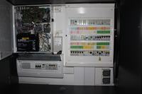
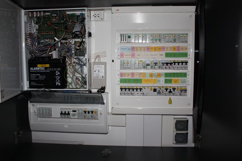
View of the alarm box and the ground-floor distribution board. Below is the alarm sub-box with relays controlled by the alarm system.
Stairs, LEDs. In the most energy-efficient mode, they consume 0.2W of power (costing around 1 zł per month).








 and water heaters, you’ll run into problems, because all household appliances these days are electronic and don’t like having their power switched on and off at will; and you can forget about tampering with the electronics too, so your project is purely theoretical.
 )
)