logo elektroda
logo elektroda
X
logo elektroda

Wiring Diagram for Converting 5-pin DIN to Jack Adapter

MaXo90 73768 16
ADVERTISEMENT
Treść została przetłumaczona polish » english Zobacz oryginalną wersję tematu
  • #1 4858948
    MaXo90
    Level 15  
    As the topic. I`m looking for a "diagram" with the name of the 5-pin DIN adapter (old audio :P ) to Jacek
    I think it`s possible because I found something like this on the net...

    Wiring Diagram for Converting 5-pin DIN to Jack Adapter
  • ADVERTISEMENT
  • #2 4859098
    hefid
    Rest in Peace
    Moved from: Diagram/instructions…
  • #4 4860707
    MaXo90
    Level 15  
    Hmm... useful but unfortunately not in this case. They are only 3-pin and you won`t see 5... but thanks anyway.
  • Helpful post
    #5 4860749
    oj
    Level 42  
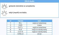
    Write where DIN5 is connected (radio, mag, amplifier) and how the audio signal should be routed: to Jack 3.5 or from Jack 3.5


    ------------
    I suspect that
    Jack3.5 (sound card output) >> DIN5 (amplifier)

    Then DIN5:
    Pin2 ground (screen)
    Pin3 L channel
    Pin5 P channel

    Jack3.5 yes:
    http://www.hardwarebook.net/images/conn/teleph35sm.gif

    In the opposite direction:
    Jack3.5 (sound card input) << DIN5 (tuner, storage)

    Then DIN5:
    Pin2 ground (screen)
    Pin1 L channel
    Pin4 P channel
  • ADVERTISEMENT
  • #6 4862053
    E.L.O.
    Level 28  
    yo rather the opposite

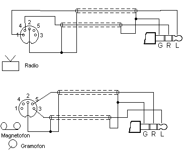
    Maybe this will help the author MaXo90 : :
    Wiring Diagram for Converting 5-pin DIN to Jack Adapter
  • Helpful post
    #7 4862075
    oj
    Level 42  
    It`s definitely not the other way around
  • #8 4862125
    MaXo90
    Level 15  
    Actually, I wanted to combine MP3 - Old Duet Dior-301 through the microphone input or tapes...
    It would simply be easier for me because the equipment works well and only Maryja and PRI receive...
    Thanks for the answer, I`ll definitely figure something out... but whether it will work is another matter...
    Greetings
  • #9 4862208
    E.L.O.
    Level 28  
    oj wrote:
    It`s definitely not the other way around

    Sorry yo You`re right.
    I corrected my post.

    Greetings
  • #10 4880950
    MaXo90
    Level 15  
    Quote:
    I suspect that
    Jack3.5 (sound card output) >> DIN5 (amplifier)

    Then DIN5:
    Pin2 ground (screen)
    Pin3 L channel
    Pin5 P channel


    It works ;] the duo plays music from MP3 and everything is fine... thank you again for your help
    and topic to be closed?
  • #11 5489900
    wlby
    Level 11  
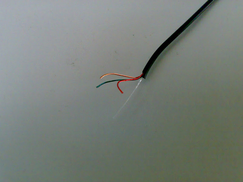
    Sorry for digging up the topic, I want to do something similar, but I don`t know the cable markings, tell me which channel is left and which is right and where is the mass according to the colors of these cables
    Wiring Diagram for Converting 5-pin DIN to Jack Adapter

    There is another thread (I don`t know what to call it), what is it??
  • ADVERTISEMENT
  • #12 5489941
    Anonymous
    Anonymous  
  • ADVERTISEMENT
  • #14 5613760
    thevice
    Level 13  
    Gentlemen, I will also add a question to the topic - I recently bought an old Unitra amplifier and I am doing the wiring. The sockets in this unit are DIN, and I wonder one thing: why did they use 5-pin sockets for the inputs?
    Therefore, when making reductions to jacks or RCA, should we do as usual, as God commanded, ground in the middle, left and right channels with 2 pins on one side (according to the drawing of the ELO connector)?
  • #15 5613813
    powerm
    Level 23  
    Do exactly as in this picture. The 5-pin DIN connector had 2 input pins, 2 output pins and a common ground. And since DIN is a standardizing organization, such sockets were charged in a standard way

Topic summary

The discussion revolves around creating a wiring diagram for converting a 5-pin DIN connector to a 3.5mm jack adapter, primarily for audio applications. Users share insights on the pin configuration for both sending and receiving audio signals. The 5-pin DIN connections are specified for various devices, including amplifiers and sound cards. The correct pin assignments are provided, with ground, left, and right channel connections detailed. Users also discuss the use of color coding for cables, confirming that gold is ground, green is left, and red is right. The conversation concludes with successful implementation of the wiring, allowing an old amplifier to play music from an MP3 source.
Summary generated by the language model.
ADVERTISEMENT