 DRF1278F Dorji.
The
Dorji Company has made
available to users of forum elektroda.pl free of charge
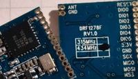
DRF1278F modules samples based on Lora Semtech
SX1278.
DRF1278F modules were tested based on documentation, manufacturer sample source code and tests performed on modules
DRF4463F https://www.elektroda.com/rtvforum/topic2667278.html last year.
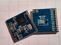
Modules PCB have a small size, description of the pin makes it easy to test.
Module using 3.3V power supply.
DRF1278F tests were based on last year's DRF4463F tests, one module works as a fixed station transmitting the results to PC via serial port (9600b/s), while the second module working as a mobile station to provide information on its position (from GPS receiver).
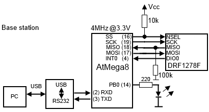
To control modules was used ATmega8 microcontroller communicates with the modules using SPI interface.
Block diagram of base station:

Block diagram of mobile station:
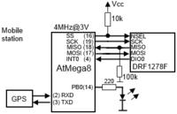
To communicate with the module, you must configure the SPI interface mode CPOL = 0, CPHA = 0 (in the Motorola / Freescale terminology).
DIO0 DIO0 DIO2 DIO3 DIO4 DIO5 output can provide information about module events.
Events from module can be serve by the microcontroller as IRQ (eg. information about the end of transmision).
The module can operate in different states.
In the SLEEP state consumes low power and allows the configuration registers. Only in this mode, you can change static configuration.
STAND-BY mode - oscillator is active, part of the RF and the PLL is disabled. Only in this mode, you can write to Lora modem FIFO.
FSTX and FSRX mode - PLL is enabled and synchronized, RF part are disabled.
TX mode - all elements needed for transmission are running, after completed transmission module returns to stand-by.
RXCONTINUOUS mode - elements needed to receive data are running.
RXSINGLE mode - elements needed to receive data packet are runing, after completed receiving module returns to stand-by.
CAD mode - module detects a preamble signal for Lora modulation on individual channels.
SX1278.
You can use module by reading and writing data to specific SX1278 registers.
Modules allows to work with many difrent modulations OOK, FSK, GFSK, MSK, GMSK, LoRaTM offering a bandwidth from 7.8kHz to 500kHz.
The main attraction of SX1278 is the Lora modulation, which is meant to allow for long range and resistance to interference. SX1278 has built-in premble detection, sync word detection, CRC engine, and packet handler.
LoRaTM.
Lora built-in modem allows to configure SF factor (6-12), error correction factor CR (1-4), which allows to optimize and increase the range and interference immunity compared to OOK or FSK modulation.
The higher SF factor demodulator can increase sensitivity but decreases transfer rate. For example for factor SF = 6 we obtain the highest transfer rate and average SNR -5 dB (using 64 symbols on a single bit). For factor SF = 12 (using 4096 symbols per bit) to give a minimum transfer rate and SNR -20 dB.
CR factor sets the error correcting codes, which add redundant data allowing the correction of transmission errors. Wen we set CR = 1 then use 4/5 coding (transmision overhead 1.25) while CR = 4 we get 4/8 coding (transmision overhead 2). The higher CR give greater resistance to interference, but lower transmission speed.
Lora modem allows to set the bandwidth factor (BW) in the range from 7.8KHz to 500kHz. For example SF = 12 (4096 symbols per bit) and CR = 1 (4/5) BW=7.8KHz we get transfer rate 18b/s, for the 500kHz bandwidth we get 1172b/s.
Wider bandwidth afect on higher bit rate, but give greater impact on other radio devices.
The baud rate is not explicitly defined, it follows from the parameters SF, CR, BW.
DRF1278F tests.
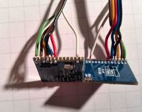
The test circuits was connected on the breadboard.
Base station:
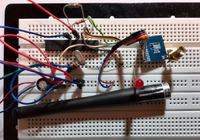
Mobile station:
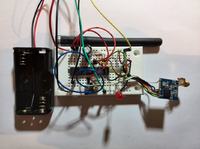
The base station periodically sends a request to the mobile station (with a specific ID) and waits for a response. The mobile station chceck ID in request, then sends NMEA data ($GPGGA) to the base station. The base station sends the received data to PC via serial port (9600b/s). The mobile station is powered by two
AA batteries (~3V).
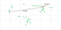
Tests were conducted with LoRa modulation, FIFO, variable packet length, SF = 7, CR = 3 (4/7), BW = 3, and the output power at ~ 5mW.
Below map from GPS coordinates of mobile station received by base station:
Below are sample code mobile and base station, based on Atmel microcontroller AtMega 8, DRF1278F module, the code was compiled using Atmel Studio. Code should be considered as an example allows you to write your production version.
DRF1278F is an advanced transciver module, comunication with module via ISP interface is easy, event can handle by microcontroler interrupts. Built-in Lora modem allows to build devices communicating over long distances while maintaining low power output and resistance to interference.
Module is interesting way to transmit small amounts of information for long distances e.g. for telemetry.


Comments
Sorry, in your code, inside function sx1276_7_8_LoRaTxPacket and sx1276_7_8_LoRaRxPacket what means PIND?? I dont see any variable with that name or a register, could you explain me? Thanks. [Read more]
@cralma PIND is a register storing input state of 8 pins in PORTD. I checking this if statement: "if((PIND&0x04)!=0){" 0x04hex is 00000100bin so simply when input bit 2 of PORTD is 1 then (PIND&0x04)!=0... [Read more]