FAQ
TL;DR: DX‑Smart DX‑WF24A (BK7238) ships with 2 MB flash, and “RX/TX headers are not for programming” — use P10/P11 to flash. Logs at 115200; BKFIL reads at 921600; OBK writes from 0x11000. [Elektroda, divadiow, post #21575328]
Why it matters: This helps makers who bought the Taobao/Superbuy DX‑WF24A kit wire it correctly, flash firmware, use AT commands, and bring up Wi‑Fi.
Quick Facts
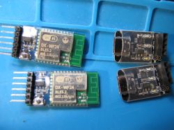
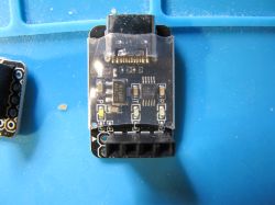
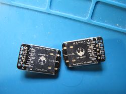
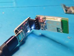
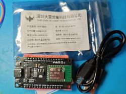
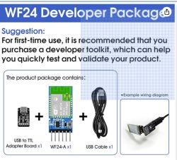
- Module/kit: DX‑WF24A (BK7238 QFN32) on a tiny breakout, plus DX‑PJ16‑V1.1 CH340 USB‑TTL and short USB‑C cable. [Elektroda, divadiow, post #21575328]
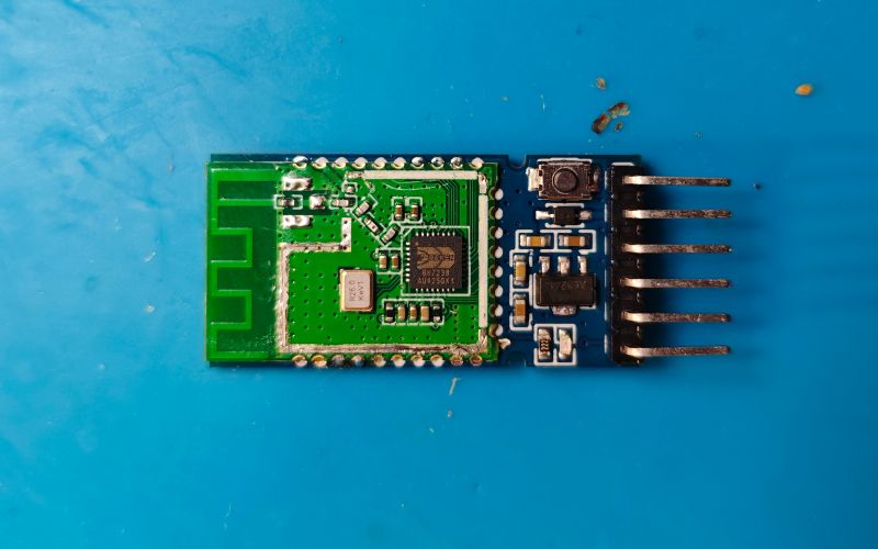
- Flash IC: 2 MB Puya P25Q16HBK, JEDEC ID 0x852015, verified under the shield. [Elektroda, divadiow, post #21575328]
- Programming: Use P10/P11 for bootloader access; board RX/TX headers are UART P0/P1 only. Console 115200, BKFIL 921600. [Elektroda, divadiow, post #21575328]
- GPIO map: P26 = WORK‑STATUS red LED, P17 = KEY button, P6 = LINK‑STATUS header. [Elektroda, divadiow, post #21575328]
- Stock firmware: AT image dump available for this module as reported by a buyer. [Elektroda, divadiow, post #21602945]
What is the DX‑WF24A bundle and what’s on the board?
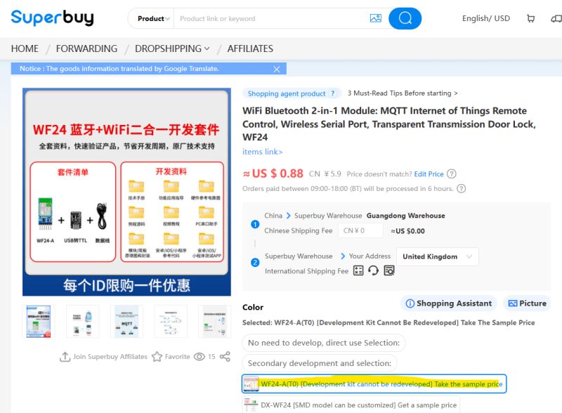
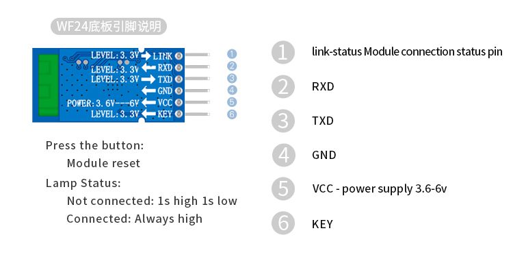
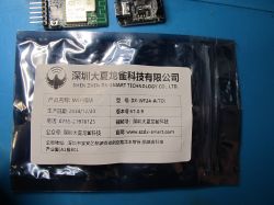
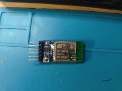
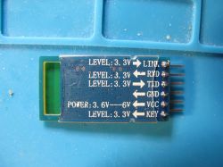
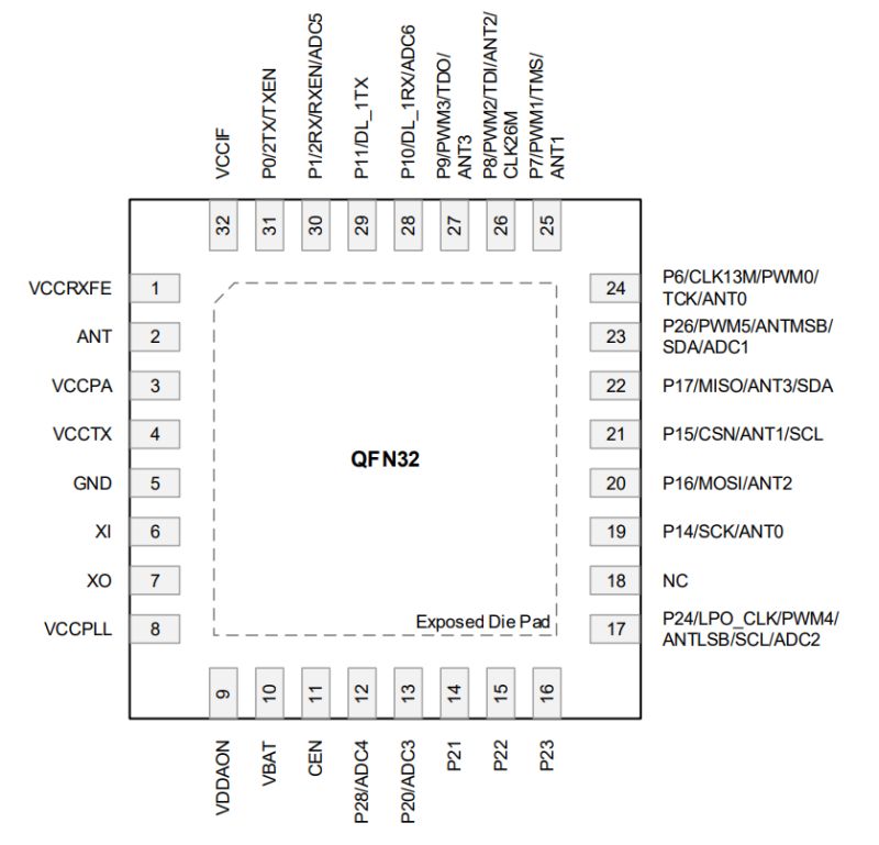
It’s a DX‑Smart DX‑WF24A module using the BK7238 in QFN32 on a small breakout. The bundle shown includes a short USB‑C cable and a DX‑PJ16‑V1.1 USB‑TTL adapter based on the CH340. The breakout exposes UART and status pins and ships with a metal RF can that was removed to confirm the BK7238. [Elektroda, divadiow, post #21575328]
Which pins are for programming—are the RX/TX headers enough?
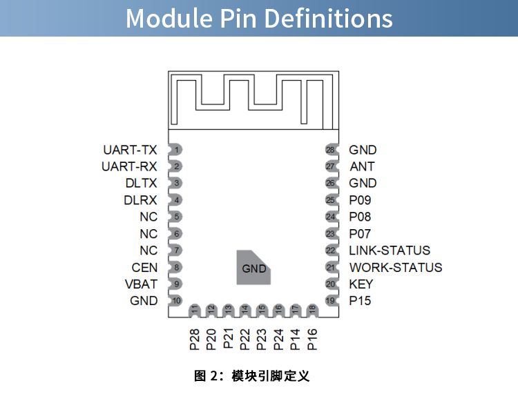
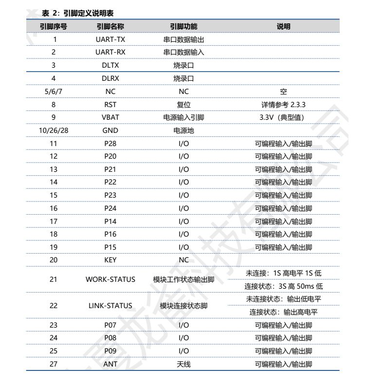
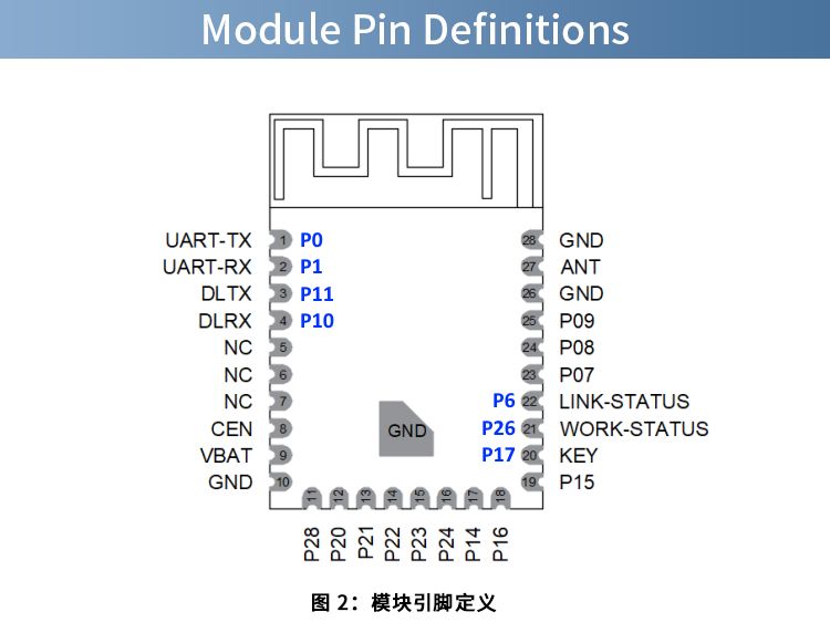
No. The board’s RX/TX headers route to UART‑TX (P0) and UART‑RX (P1) for console. To read or write flash you must solder to P10 and P11, which are the bootloader pins. This catches many first‑time users. “RX/TX headers are not for programming.” [Elektroda, divadiow, post #21575328]
How do I dump or flash firmware on BK7238 with BKFIL or Easy Flasher?
- Wire P10, P11, VCC, and GND to your USB‑TTL (the DX‑PJ16 CH340 works).
- Power the module, then open BKFIL/Easy Flasher and select 921600 baud.
- Example dump: bk_loader read --portinfo 63 --baudrate 921600 -f 0-200000. This produced a valid 0–0x200000 read on the sample module. [Elektroda, divadiow, post #21575328]
What UART speeds should I use for console and flashing?
The BK7238 prints a boot console on P0 at 115200 bps. A typical read command used 921600 bps for faster transfers with BKFIL. Expect lines like BK7238_1.0.14, RT‑Thread OTA, and go os_addr(0x10000) on boot. [Elektroda, divadiow, post #21575328]
Does the DX‑WF24A ship with AT firmware, and can I test it over a terminal?
One buyer reported the module came with an AT build and shared the image. You can connect the CH340 to a serial terminal (e.g., SSCOM) and send AT commands to verify responsiveness. If it does not respond, consider reflashing the shared AT binary. [Elektroda, divadiow, post #21602945]
Which AT commands appear in the stock image?
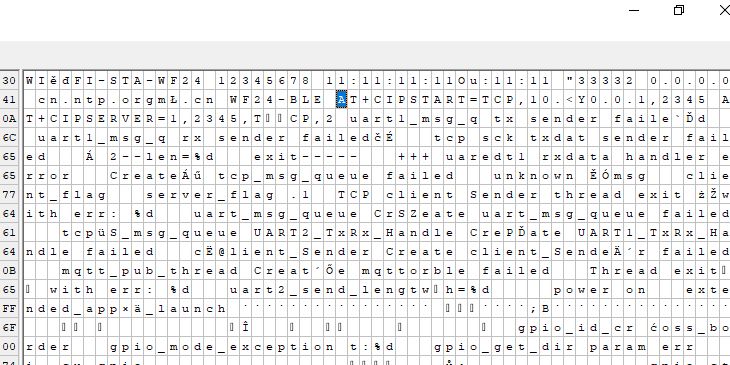
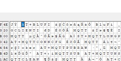
Binary strings show common tokens, including AT, AT+RST, AT+GMR, AT+CWJAP, AT+CIPSTART, and AT+CIPSEND. That indicates a typical Wi‑Fi join and TCP/UDP stack is present in the image. “There are some AT mentions in the binary strings.” [Elektroda, p.kaczmarek2, post #21602949]
What’s the simplest way to get Wi‑Fi working for a basic serial‑to‑Wi‑Fi test?
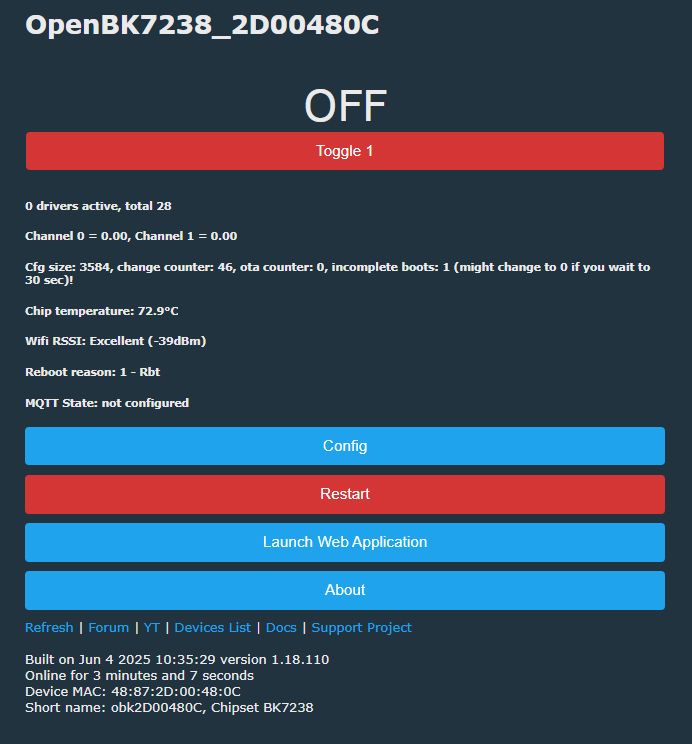
Two paths: 1) keep the stock AT firmware and send AT join commands from a terminal; 2) reflash OpenBK7238 (OBK) if your goal is rapid prototyping without vendor AT. As one expert noted, using OBK may be easier depending on your project. [Elektroda, p.kaczmarek2, post #21602913]
Do I need an “encryption key” to run OpenBK7238 on BK7238?
No. Keys read out under some tools are artifacts of read‑protection. “The ‘encryption key’ mentioned is not really an encryption key… they all run well with unencrypted OBK.” You can proceed without supplying a special key. [Elektroda, p.kaczmarek2, post #21577167]
From what offset do I flash OpenBK7238 on this module?
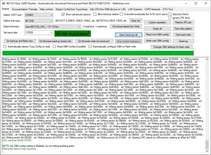
OpenBK7238 was reported to write successfully starting at 0x11000 on the DX‑WF24A. Use the correct pins (P10/P11) and the USB‑TTL to perform the flash operation. Confirm with a short console boot test after programming. [Elektroda, divadiow, post #21575328]
Which pins control the LED, button, and link‑status on DX‑WF24A?
P26 drives the WORK‑STATUS red LED. P17 is the KEY button input. P6 is exposed as the LINK‑STATUS header. These defaults are helpful when mapping indicators in firmware or testing AT status behavior. [Elektroda, divadiow, post #21575328]
What boot log should I expect on stock firmware?
Expect a 115200 console showing BK7238_1.0.14, RT‑Thread OTA package initialization, and a branch to go os_addr(0x10000). You may also see a simple “power on” line on P0. This verifies the module is alive before flashing. [Elektroda, divadiow, post #21575328]
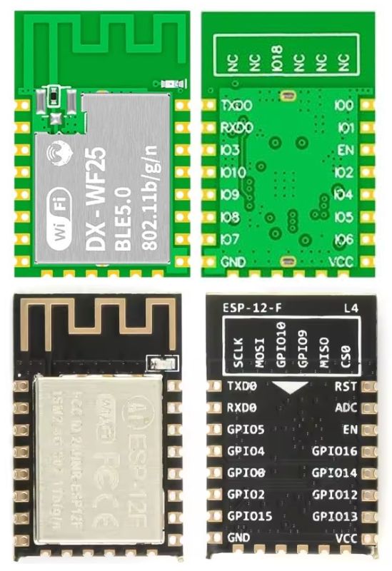
Is DX‑WF25 (ESP‑C3) a drop‑in for ESP‑12F pinouts?
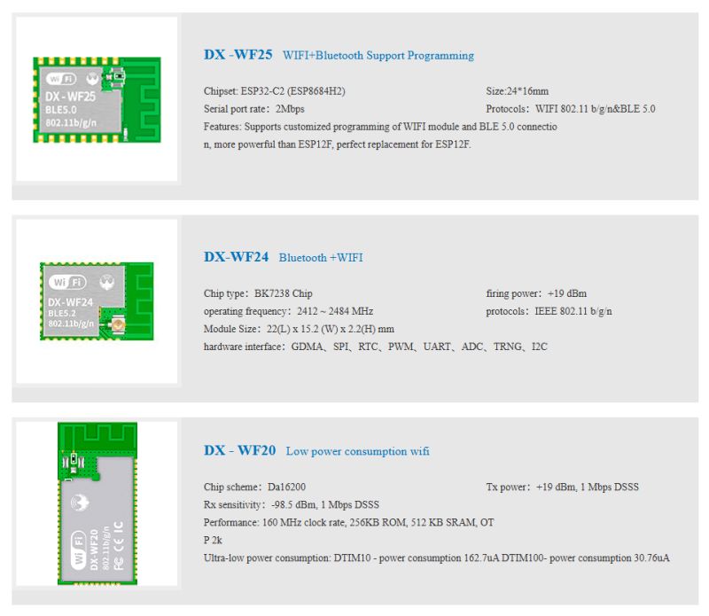
Yes, it’s presented as a perfect ESP‑12F replacement. A user confirmed power, reset, and UART1 pins match. This helps migrate ESP‑12F designs to ESP‑C3 modules without PCB changes. [Elektroda, divadiow, post #21583411]
What is the Renesas DA16200 mentioned by DX‑Smart?
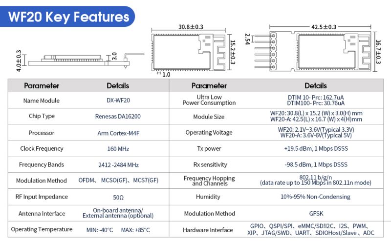
DA16200 is an ultra‑low‑power Wi‑Fi SoC designed for battery‑powered IoT devices. It targets long‑life standby and active modes with integrated TCP/IP networking. You may see it in other DX‑Smart module families. [“DA16200 Ultra-Low-Power Wi‑Fi SoC”]
Where can I browse more DX‑Smart Wi‑Fi modules?
DX‑Smart lists multiple Wi‑Fi modules on its catalog page. The forum thread links directly to their Wi‑Fi module lineup for quick comparison and specs. Start there to find related parts. [Elektroda, p.kaczmarek2, post #21577840]
