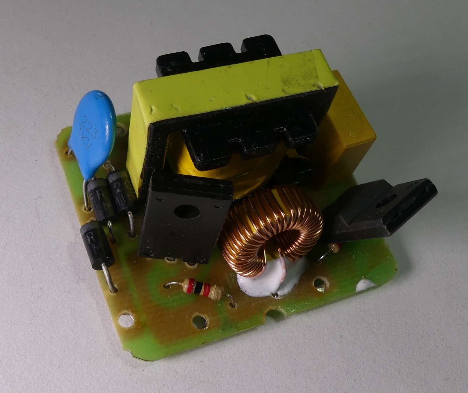
The module you see in the picture can be found on auction sites
as a 40W 12DC to 220VAC converter . Seeing the design of the device in the photo, I wasn't expecting much for the price of $ 2. I was hoping that the module would work and allow you to power a 230V GU10 compact fluorescent lamp or "bulbs".
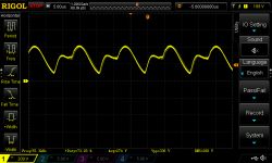
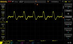
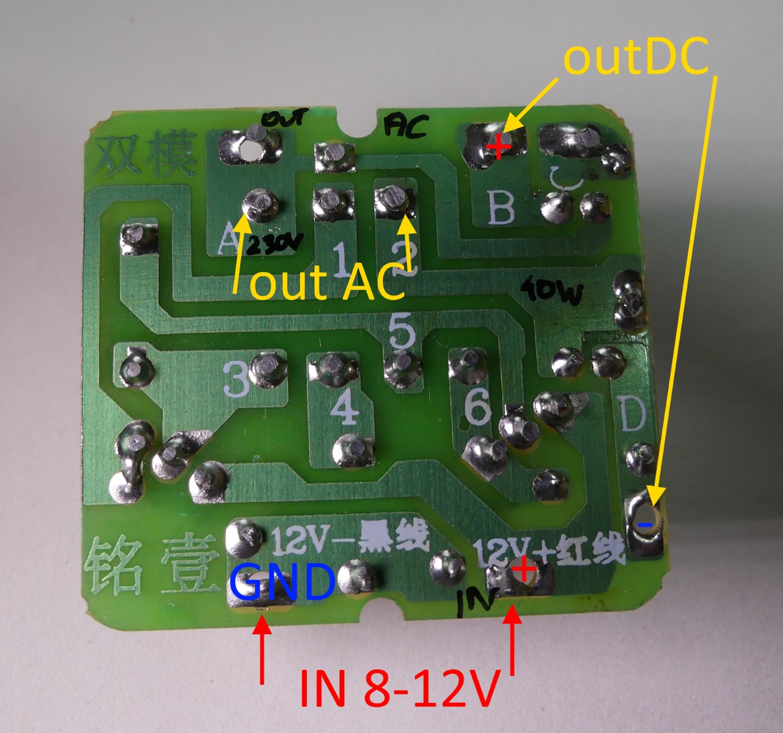
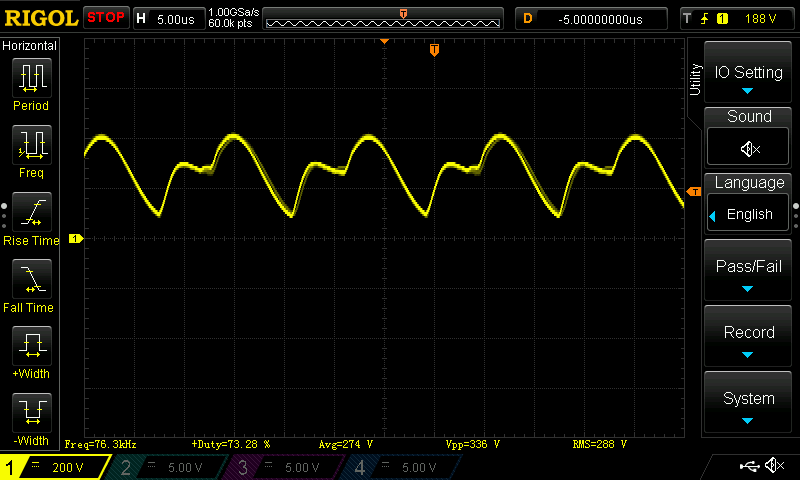
After starting the module, as expected, it turned out that a ~ 40kHz sine wave appears on the secondary side of the transformer, the effective voltage may reach several hundred volts in no-load condition. As the power consumption increases, the output voltage drops to the 220V visible in the description and even less 90-100V. On the board you will find the fields marked -12V (GND) and + 12V where we connect the 8-12V supply voltage. In points B and D we get a rectified output voltage of 100-300V.
 Be careful when starting up, because of the voltage threatening to health and life in the system.
 When working without load, the system consumes ~ 68mA, supply voltage 12V, the rectified output voltage may reach even 400V, such configuration should be avoided.
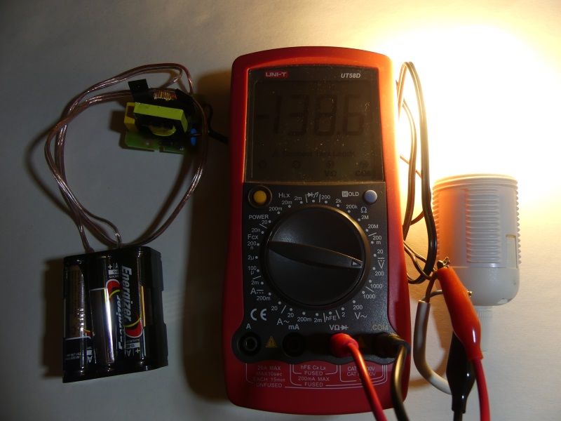
After loading the LED GU10 8W output, 0.87A current flows at the input of the system at a voltage of 12V, while the output is ~ 260V and 30mA:
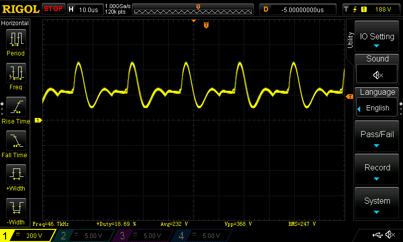
After connecting two LED GU10 8W, a current of 1.73A flows at the input at 12V, the output is 230V and 66mA:
The efficiency of the system is ~ 73%, the transistors heat up quite a bit during operation, a small heat sink should allow the heat to dissipate. The connected light sources worked satisfactorily at the input voltage of 9-12V, while they went out completely at about 5V.
To sum up: a dangerous system (no output voltage control),
lack of documentation,
errors in the auction descriptions,
information suggesting that the output will be 220V AC (which suggests the mains voltage),
in fact we get an undefined high frequency AC voltage, or DC.
When connecting an unloaded simple AC-> DC converter as a receiver, there is a risk of explosion of the electrolytic capacitor (too high supply voltage).
With careful use, the module can be useful to power 230V light sources, and the board can fit in the base of the lamp holder. You can use a 12V installation or even a battery power supply (e.g. 6x1.5V AA) for power supply. If we install an effective 230V LED luminaire, which is rarely turned on for a short time (e.g. above a mirror), the module can replace (or delay)

) 230V power supply, wall hammering, cable routing, etc. works.


Comments
What more to expect from a self-excited push-pull converter (ZVS)? This is good for direct supply to fluorescent lamps. It is not suitable for powering LEDs or energy-saving ones, because the rectifier... [Read more]
Simple construction The price is amazing :) $ 2 I wonder how much does it cost to produce a dollar? Through the Chinese [Read more]
Could be used to power NIXIE lamps :) [Read more]
The price attracted me to this module. There are fast diodes at the output of the module and a rapidly pulsating rectified voltage enters the LED "bulb" with slow rectifying diodes. When powered from a... [Read more]
... and cheaper. To power nixie, milliamps are needed, so it can be done better and cheaper. In my clock (it has been working continuously for over 10 years), a converter made on the MC34063, a choke,... [Read more]
Additionally, the MC34063 will provide stabilization / control of the output voltage. [Read more]
That's it. I forgot to mention the PR that I set the output voltage with in the BOM ;-) [Read more]
I will add that the theory with fast diodes at the output of the module and "slow" diodes in the LED "light bulb" is correct, I have confirmed it in practice, the 10-47uF electrolytic capacitor at the... [Read more]
It was necessary to illuminate the meter. The light bulb shines through the image and readings are barely visible. [Read more]
The subject is as old as the world, but see how with 2 $ (about 8 PLN) + let's assume the shipment (because it is different and the price is free) it changes in two years. Price: #Aliexpress 71.62... [Read more]
The price has not changed, you chose the most expensive offer you could find. You can still buy this miracle for $ 1.6 (or about PLN 7) with free shipping ... https://obrazki.elektroda.pl/76575953... [Read more]
Hello. Well, the fact that I clicked on the link from the post earlier and it popped up. If you say so, it is possible it is. Send the link please - just out of curiosity. I wonder what transistors are... [Read more]
Have you seen the printscreen I pasted? But please, I googled it for you . [Read more]
Thank you. And the printscreen did not appear for me (maybe because I'm on the phone). Ok. Cool. It's not about questioning your opinion. Best regards. [Read more]