Tutorial sets up SDCC and GPUtils for PIC18F2550 development, covering Windows, Ubuntu, command-line builds, and Code Blocks integration.
It shows how to install the tools, add them to PATH, verify sdcc -v and gband -v, and compile PIC code with sdcc.exe --use-non-free -mpic16.
Examples mention SDCC 3.9.0, a 220nF capacitor on VUSB, a 10k RESET pull-up, and the libc18f.lib library for delay1ktcy.
A blink example compiles to a .hex file and runs on a breadboarded PIC18F2550 via PICKIT3, while apt-get SDCC on Ubuntu cannot target PICs.
Generated by the language model.
Here I will describe step by step installation, configuration and use free compiler SDCC for creating programs for PIC microprocessors. The whole thing will be in the form of a detailed tutorial. Due to the length of the whole tutorial, I will divide it into separate topics . In later parts I will try to describe the use of most popular peripherals, libraries, w SDCC by example PIC18F2550 . How many parts will eventually come out and what will be discussed depends to a large extent on what the comments will be. Of course, I accept suggestions, so if someone wants me to discuss, for example, PIC communication via I2C with a selected cube/module, please let me know.
This topic is part 1, that is Setting up the working environment . Here we go.
What is what? SDCC (Small Device C Compiler) is a free, open source compiler for many families of 8-bit microprocessors, including: - PIC16F/PIC18F (which we will cover in this topic) - 8031, 8032, 8051, 8052 Intel - DS80C390 from Maxim/Dallas - 68HC08 and 68HCS08 from Motorola/Freescale/NXP - STM8 from STMicroelectronics - PDK14 and PDK15 from Padauk Technology - Zilog Z80, Z180, eZ80 SDCC is available under the GPL license. It supports Windows, Linux and macOS platforms
GPUtils it is a collection of tools for PIC microcontrollers from Microchip. Includes programs like gpasm, gplink, gplib. It is available under the GPL license on Windows, Linux and macOS platforms. GPUtils is required by SDCC if we want to compile batch for PICs.
What will the tutorial cover? In this tutorial (and in the next part that is on the way) I will try to include: - step by step installations SDCC along with setting PATH paths on Windows - step by step installations GPUtils along with setting PATH paths on Windows - step by step package installation SDCC for PIC along with setting PATH paths on Ubuntu - presentation of the method how to check whether SDCC/GPUtils is configured correctly - a short description of how to compile programs with help SDCC - detailed examples of programs done in SDCC For PIC18F2550 with the help of libraries available in the compiler itself and on the network There will be a tutorial practical , i.e. I will focus more on how to get results than on how what works internally. The instructions here will be as detailed as possible (without skipping steps, etc.), but I expect the reader to be able to use the search engine and other sources of knowledge as well. And above all - the tutorial does not replace school and books!
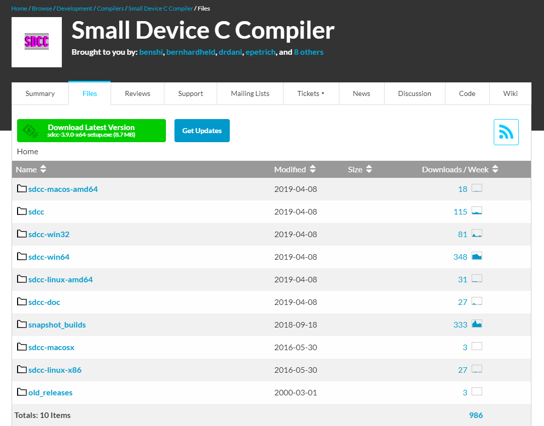
Windows - Installing SDCC and GPUtils with the help of installers homepage SDCC is hosted on SourceForge. There is documentation on it SDCC , manual in PDF, download links and the source code of the compiler itself (it is open source). http://sdcc.sourceforge.net/index.php Itself SDCC we can download from here: https://sourceforge.net/projects/sdcc/files/
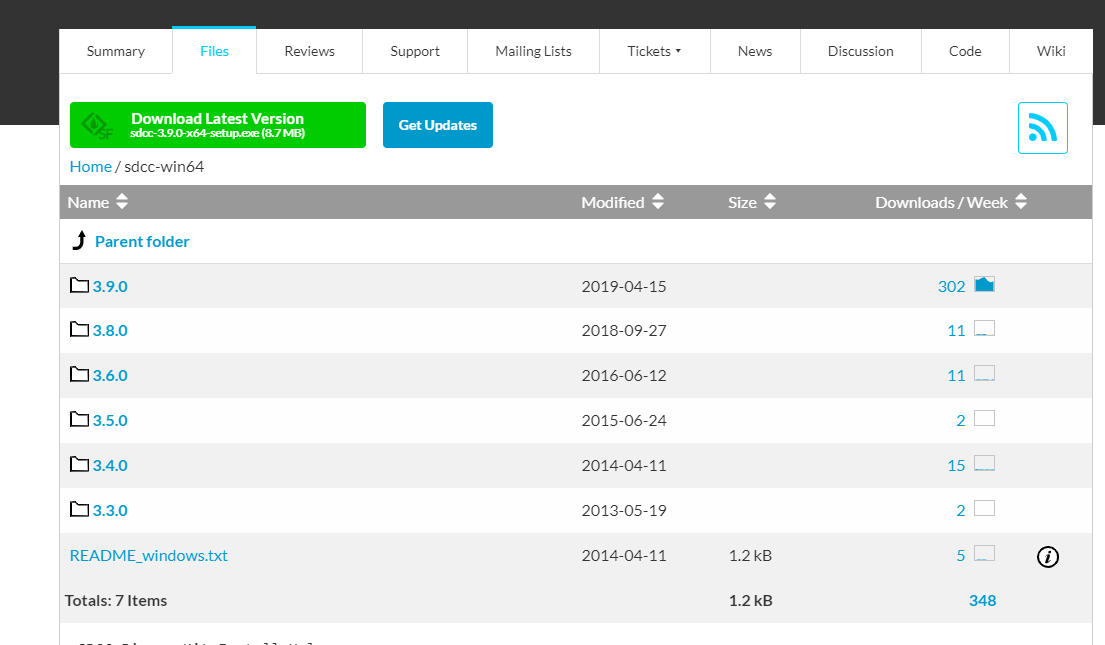
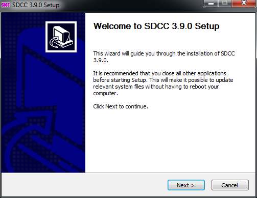
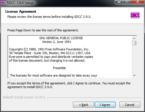
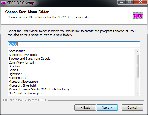
I will describe the installation process in detail here. First, let's go to the link above. We choose the latest version (at the time of writing it is 3.9.0 from 2019-04-15): We start the installation process: By default, we read the entire License, SDCC is licensed GPL v2 . We select the Start Menu Folder and the full version of the installation:
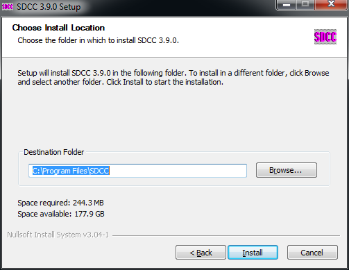
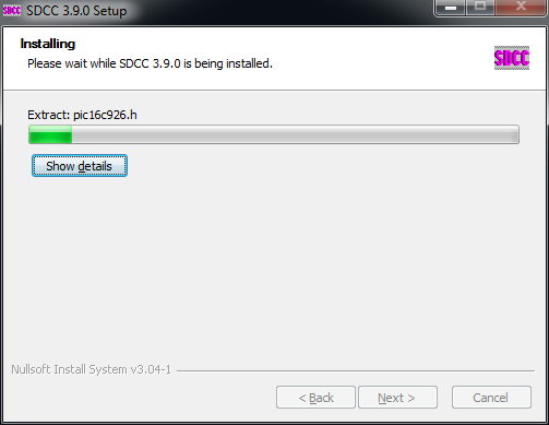
Here it is worth changing the place where we will install SDCC . By default, the installer wants to put the compiler in "C:/Program Files/", but on Windows I experienced a problem with starting SDCC with a space in this name, so it's most convenient to install the whole thing to, for example, "C:/SDCC/". We are waiting for the installation process SDCC will end: Finally, the installer automatically adds the SDCC path to the PATH environment variable:
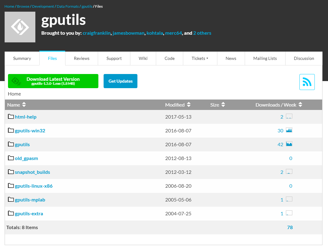
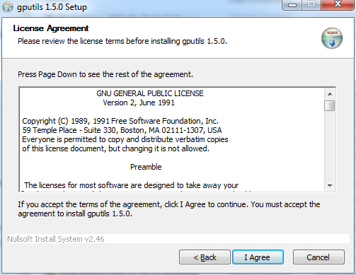
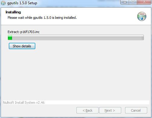
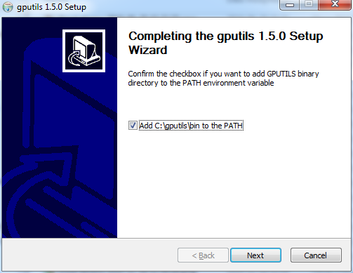
Now we need to install separately GPUtils in which it is located gband.exe necessary to compile the batch for PIC. GPUtils also has a page on Sourceforge: https://gputils.sourceforge.io/ You can download them from here: https://sourceforge.net/projects/gputils/files/ We start the installation: GPUtils It is also licensed under the GPL. We read the license and accept it: We choose the full version of the installation: We are waiting for the installation process to finish: Finally, as with SDCC , the installer gives us options to automatically add a folder GPUtils to system paths:
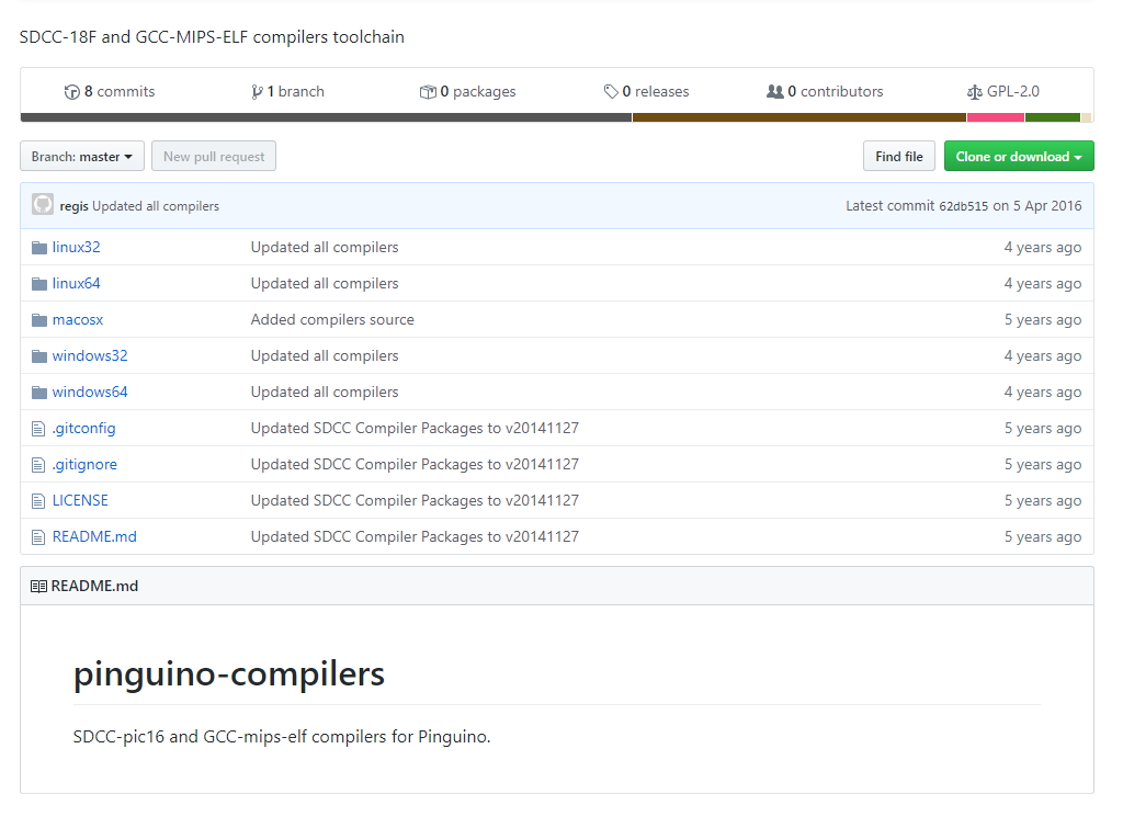
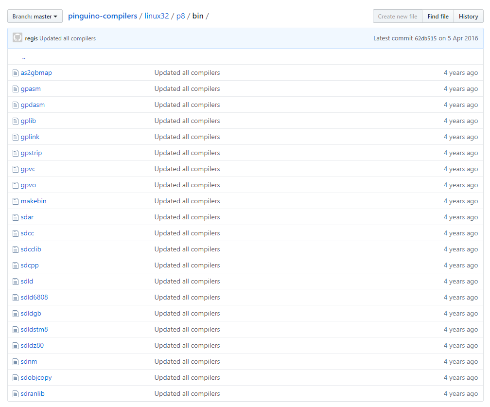
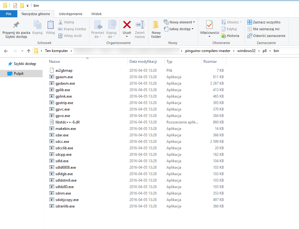
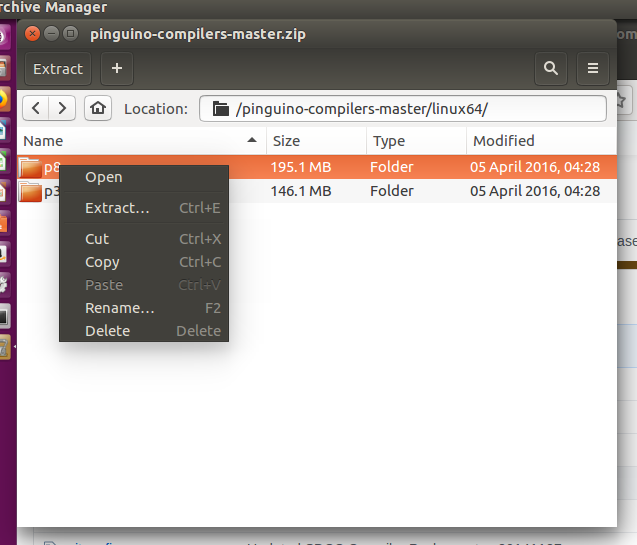
Windows - Alternative way to install SDCC and GPUtils - Pinguino Compilers penguin (a free, open-source Arduino equivalent for PIC) has a ready-to-use package of compilers for 8 and 32-bit PICs. It is also in it SDCC along with all the necessary accessories. This pack already includes GPUtils ( gband.exe , and others), so you don't have to install them separately afterwards. It can be downloaded for free from github (binaries are also available there): https://github.com/PinguinoIDE/pinguino-compilers This is a full set of compilers ( SDCC and MIPS ): There are even Linux binaries there: Just in case, I'm putting a backup of the above repository here (at the time of writing this post): Windows 32: pinguino-c...dows32.zip (29.01 MB)You must be logged in to download this attachment. Windows 64: pinguino-c...dows64.zip (29.42 MB)You must be logged in to download this attachment. Linux 32: pinguino-c...inux32.zip (23.99 MB)You must be logged in to download this attachment. Linux 64: pinguino-c...inux64.zip (25.64 MB)You must be logged in to download this attachment.
Installation in this way is only about unpacking the package where we want, but you need an environment variable %PATH% set manually. Otherwise, the system will not recognize the command sdcc , etc.
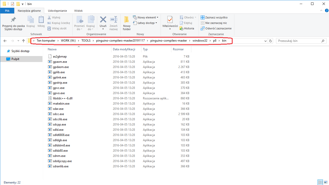
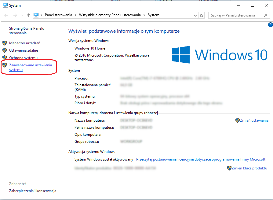
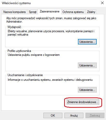
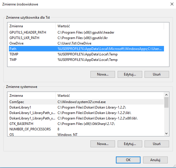
Windows - Set the PATH environment variable for SDCC If we downloaded SDCC from the repository Pinguino-compilers or some other way without using the installer then you may need to manually add the path to SDCC to the variable PATH . This is needed for Windows to recognize the command sdcc being in any folder. To do this, first we write down in which folder we have the compilers installed (more precisely: what is the full path to the bins from the folder SDCC ). For example: And then we add it to %PATH%, either through the Windows interface or through the command line. Method 1: Adding a folder to the PATH via the Windows interface It's pretty much the same on each version. On Windows 10, we first open the properties of the computer: Then we open the "Advanced system settings", the "Advanced" tab, click on the "Environment Variables" button there: Now we see the editor of all environment variables on Windows. We select the Path variable there: Click on ''''Edit'''' to go to the editor of all tracks in this variable. Each of them is here separately, we do not need to use semicolons. We add a new one using the ''''New'''' button, after which we must confirm the changes by clicking ''''Ok''''.
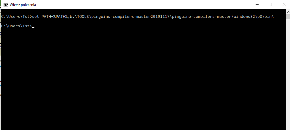
Method 2: Adding variable to PATH via cmd console We have a command there set NAME=value which sets a variable with a given value NAME to a given value. You can also display the current value of the variable there by typing % NAME % . We can therefore use these two mechanisms at once to add another path to the system paths. So we type in the console:
Where PATH_TO_SDCC is the full path to SDCC , to the folder bin , full. This is enough to add the path to PATH and it will be remembered after restarting the computer.
We proceed similarly with GPUtils . We also add the path to PATH (if it's not there). In case of Pinguino-Compilers we don't need to add the paths twice because there i sdcc.exe and gband.exe is in one folder:
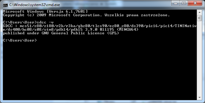
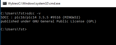
Windows - Check SDCC and GPUtils installation If everything went well (and the SDCC folder path was added to the PATH) then the command console should recognize the sdcc command. You can check this by typing sdcc in it, or eg sdcc -v to display the installed compiler version. In the case of the Pinguino version, the result of the sdcc -v command may be slightly different:
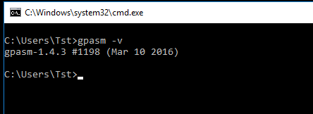
Similarly, we check if the tools from GPUtils, especially gpasm.exe, are correctly visible. Enter the command in the console gband -v .
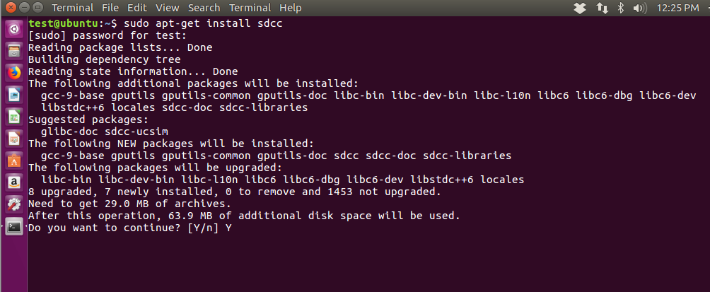
Ubuntu - Install SDCC/GPUtils One might think that SDCC / / GPUtils can be installed on ubuntu via apt-get . Nothing more wrong! Actually, apt-get lets you download SDCC on ubuntu but so downloaded SDCC Unfortunately, it does not support PICs . Screenshots from the ''''incomplete''' installation in the spoiler SDCC By apt-get :
Spoiler:
Starting installation via apt-get: End of installation:
The screenshot below shows how such an installation ends SDCC on Ubuntu - after checking the version with the "sdcc -v" command, you can see that DRINK are not supported, and the compilation command itself results in the error "cannot generate code for target ''''pic16''''". Such an SDCC is of no use to us. The problem is that some of the files associated with the PICs are not under a license compatible with the repository policy apt-get so we have to download our compiler manually.
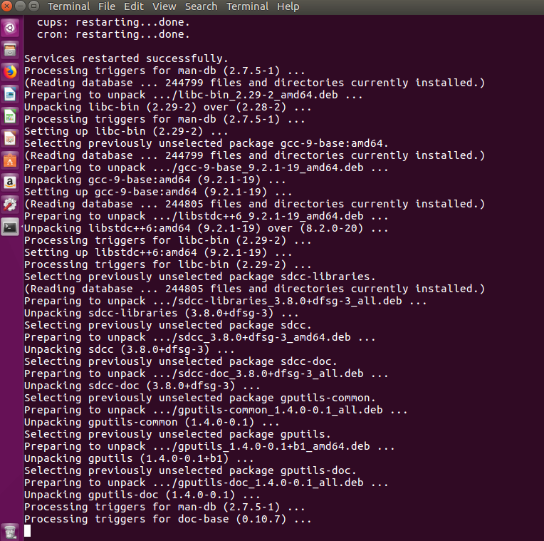
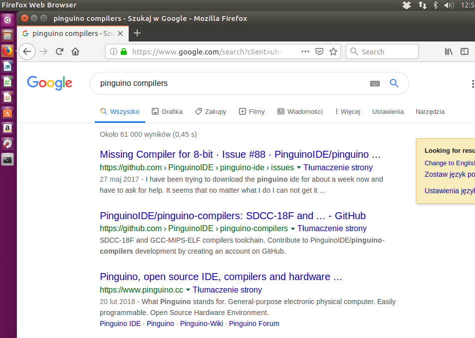
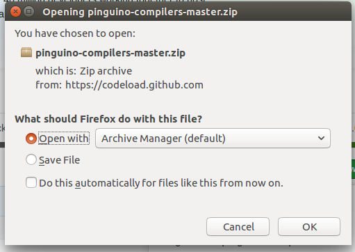
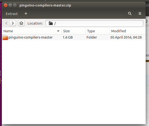
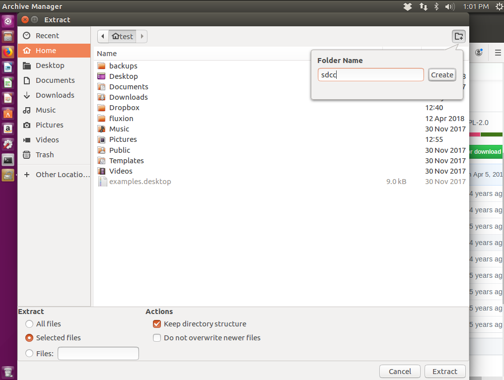
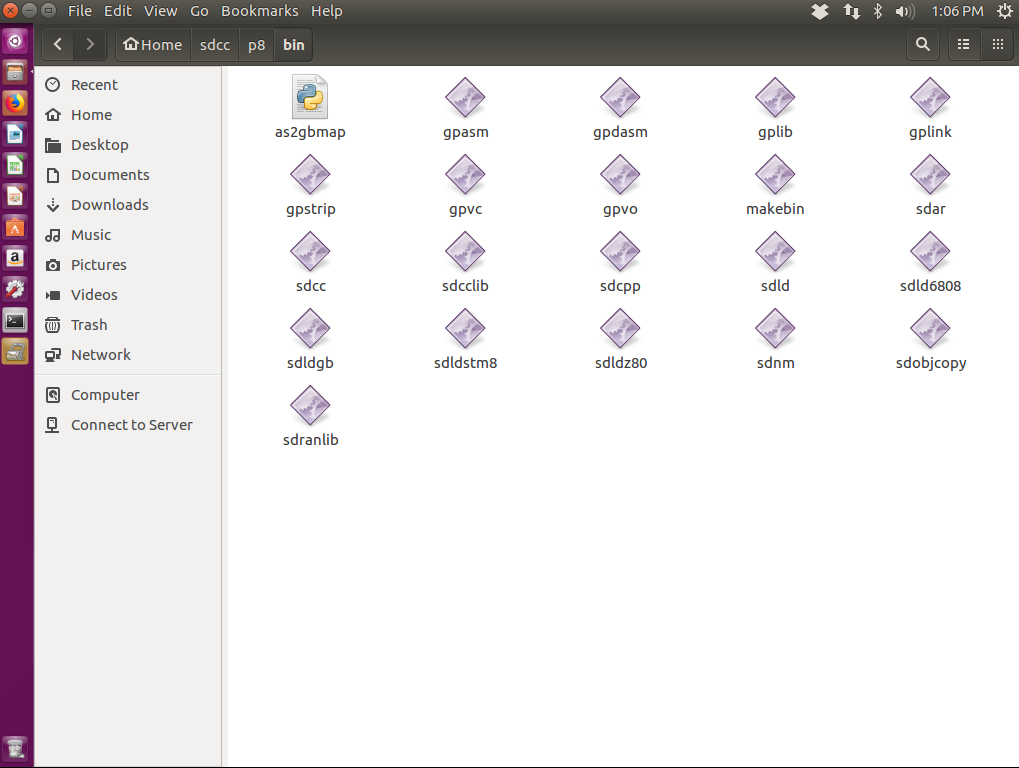
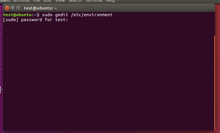
So SDCC for Ubuntu under PICe must be downloaded manually, either from the SDCC website itself or from the one mentioned earlier Pinguino-compilers . I will describe here how to download SDCC from Pinguino-compilers (it is already compiled there, both for 32-bit and 64-bit Linux). We open the appropriate Github repository on Ubuntu, from where you can download Pinguino compilers , here: https://github.com/PinguinoIDE/pinguino-compilers We download the entire repository, although we only need the p8 (8-bit) binaries for 64-bit Linux. We save the archive file. We extract from it only what is needed for us (here: folder p8 from the folder linux64 ): Choose a folder where we will unpack it. I unpacked it to /home/test/sdcc/ (the p8 directory was created there, and bin in it). It's actually not that important where we put it, because we'll configure the Linux PATH to point to the bin folder with the compiler anyway. After unpacking, we see that we already have executable files sdcc , gband and other necessary tools. Ubuntu - Setting the PATH environment variable for SDCC Contrary to appearances, setting this path on Linux systems is not as analogous to Windows as it might seem. In my case, assigning a new value to PATH from the Ubuntu console did not work, because the system forgot its value after rebooting. That is, the same set PATH=%PATH%;/new/path/ not enough. Only the file editing method worked correctly for me /etc/environment . 1. We open this file as administrator: 2. We add the path to SDCC there: 3. We restart the system From now on, whenever you turn on Ubuntu, it should know the path to SDCC .
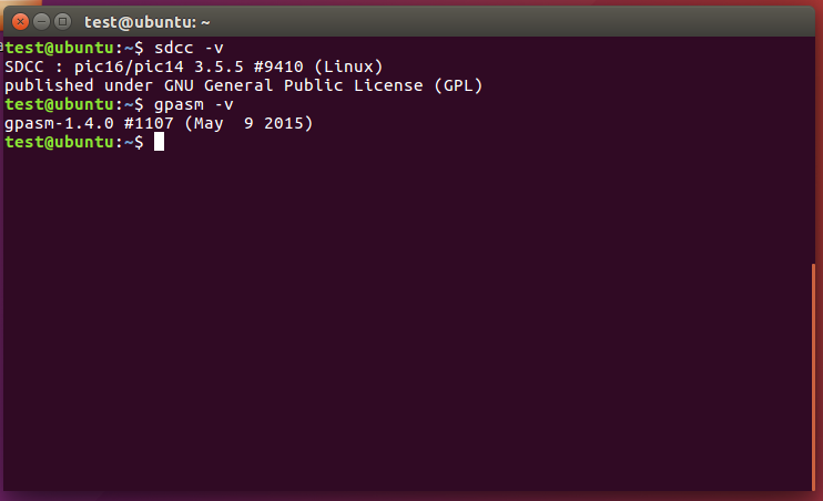
Ubuntu - Verification if the installation was successful As with Windows. We can check the SDCC/GPUtils installation by typing commands in the console sdcc -v and gband -v . The screenshot shows the correct expected result. Note that the command sdcc -v shows explicitly that this version of SDCC supports it pic16/pic14 .
First test build Now that we know that SDCC and GPUtils are added to the system paths, we can check if the compilation process itself is working. We take some simple code, for example blink for PIC18F2550:
Code: C / C++
Log in, to see the code
(Later in the tutorial, this code will be arranged in more detail).
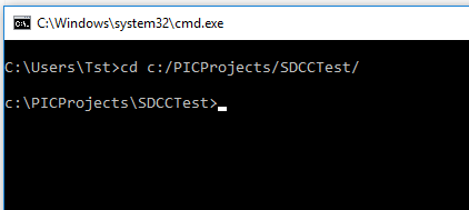
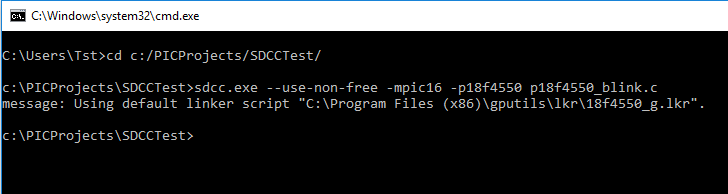
We save it in a file with the .c extension in a folder of our choice, e.g. on D:/PICProjects/SDCCTest/ . We open the console, go to this folder with the help of the cd command: And we compile with SDCC with the help of the command:
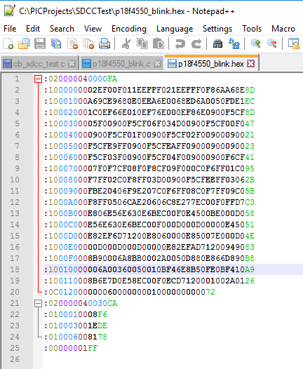
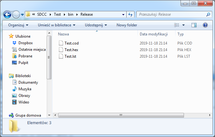
The result should be a .hex file ready to be uploaded to the PIC. This is the correct batch ready to be uploaded to the PIC: This is what a PIC batch looks like when compiled in .hex format.
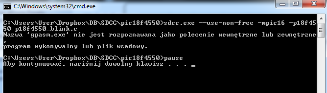
If the build fails and you get the error " The name ''''gpasm.exe'''' is not recognized " means either we don't have %PATH% set to the bin folder of GPUtils, or we didn't install GPUtils at all.
We are looking at SDCC commands We already have the compiler installed. Now we will analyze in detail the command with which we compile the C code into a ready-made file .hex for PIC. In its simplest form, it looks like this:
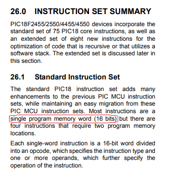
That's all it takes to compile our program. p18f4550_blink.c - this is of course the name of our code file. It can be basically anything, but it's worth keeping the .c extension in it. Switch --use-non-free allows the compiler to use Microchip's PIC libraries and is needed here in most cases. mpic16 here means that we are compiling for the PIC18F family. Yes, mpic16 stands for 18F - these 16 are there because the core of the PIC18F family has a 16-bit instruction word. (source: PIC18F4550 datasheet)
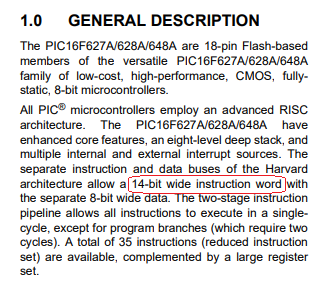
Similarly, there is an option mpic14 . With its help, we compile for the PIC16F family: sdcc.exe --use-non-free -mpic14 -p16f628 p16f628_blink.c mpic14 here means that we are compiling for the PIC16F family. Yes, mpic14 stands for 16F - these 14 are there because the core of the PIC16F family has a 14-bit instruction word. (source: PIC16F628A datasheet)
Using the appropriate option (mpic14 vs mpic16) is necessary, e.g. others it depends on what #include files are available (for example, pic18fregs.h is only on the PIC18F family). Option mpic14 also supports the family PIC12F *, e.g PIC12f675 .
Compilation of a project consisting of several files in SDCC Now you should consider how to compile a project composed of several files with the source code. Suppose we have two files. - test_blink_file.c - p18f4550_blink_multipleFiles.c You definitely can't do it like this:
This results in a rather disturbing error that reads " at 1: warning 120: cannot compile more than one source file. file ''''test_blink_file.c'''' ignored ".
But that's not a bad thing - SDCC can compile a project consisting of many files, you just need to break the compilation into separate stages.
In this method, we compile each additional code file separately, and at the end we provide the file with the main function and the results of previous compilations. It is very important that the function file main() enter here first.
You can separate the whole process even more - compile each code file with a separate command (also a separate file with main() ) and then just combine them. However, it still requires manually adding a .lib file with functions for PIC18F.
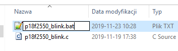
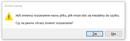
Organization of work - scripts for compilation Of course, you don't always have to manually enter commands into the console. You can make a .bat batch script (on Windows; .sh on Linux) that will do what you want for it. A .bat script is simply a text document and is created just like a txt file: Enter its name (with the .bat extension): In the event of such a message, we confirm that the file should have the .bat extension: Then we edit it as a text file. You can to the scripttype those commands that are normally executed in the console, but you don't have to worry about paths - just specify relative ones. So if the code file is in the same folder as the script, we only enter the name of the code file, etc. In scripts, you can also use echo to display a message and pause to stop the window from hiding. Finally, one of the simplest build scripts looks like this:
Running it starts the console window and the compilation process in it. '''' command pause '''' makes the window stay and wait for closing after compilation, so we can check if the compilation was successful.
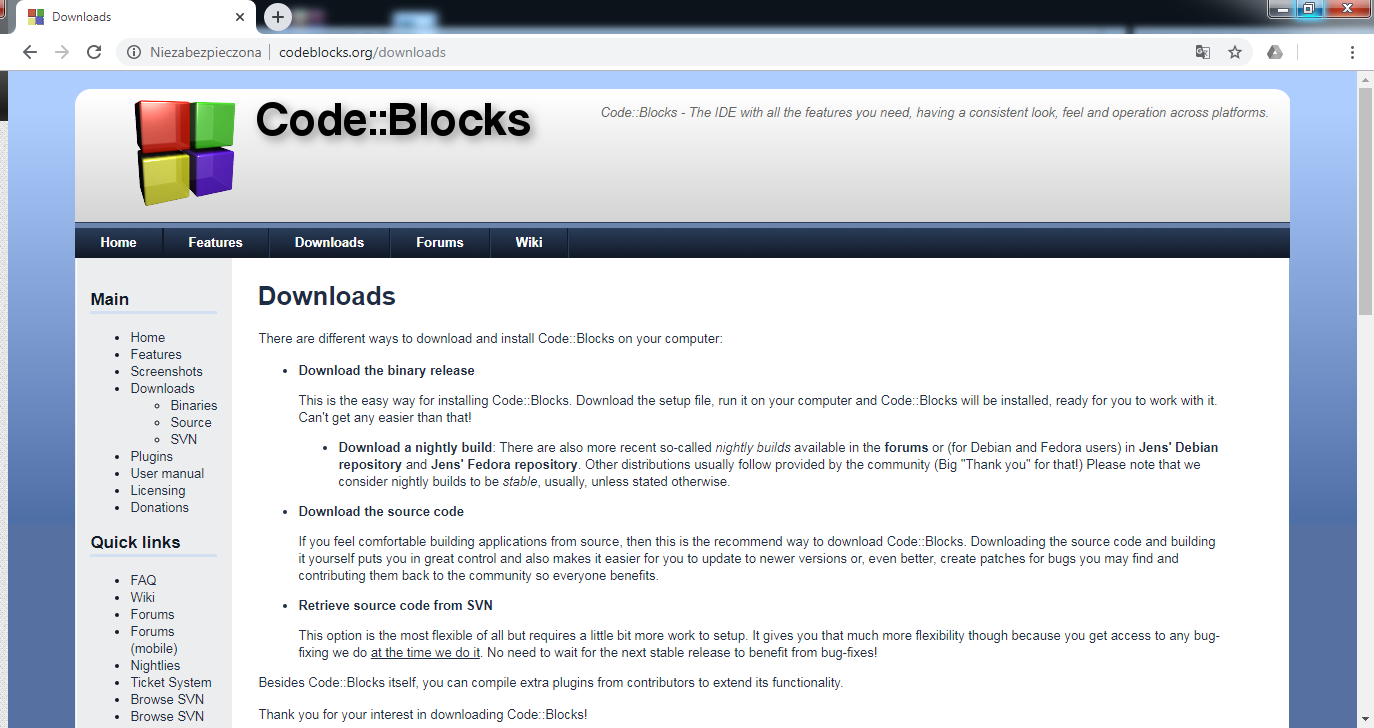
An alternative to writing code in Notepad - SDCC in Code Blocks Using an integrated coding environment is not necessary here, but it can be quite convenient. Therefore, I will now show how you can configure Code Blocks to work with the compiler SDCC and writing programs for PICe. SDCC and GPUtils must be installed beforehand according to the instructions in this topic! We start by downloading Code Blocks: http://www.codeblocks.org/downloads
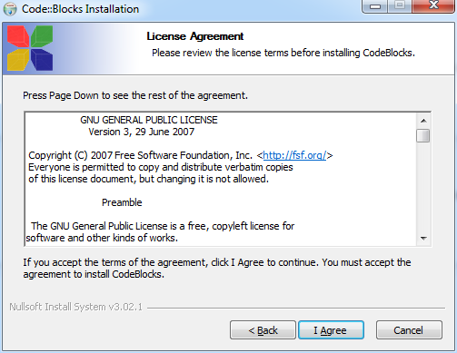
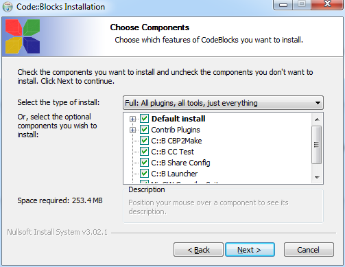
At this stage, we can download the clean version of Code Blocks (without any compiler), as well as the one with MingW (except that the MingW compiler itself will not be useful to us - we will use it anyway SDCC . This is just in case we want to use CB for Windows programming as well.) But I emphasize that Code Blocks allows you to have different compilers at once ( MingW will not interfere with SDCC ). We install Code Blocks through the Windows installer. Code Blocks is of course also GPL licensed. We choose the full installation; it's only 250 MB anyway.
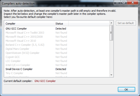
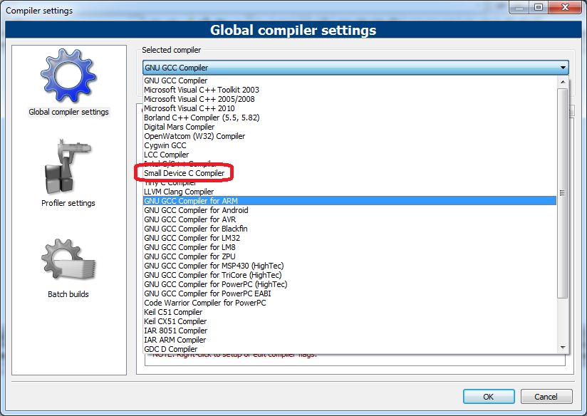
The first time you run Code Blocks it automatically detects which compilers you have. It should detect presence SDCC , but even if it doesn't detect it, it's no problem - you can set the path manually in the settings. By the way, the picture above shows how many compilers it supports Code Blocks .
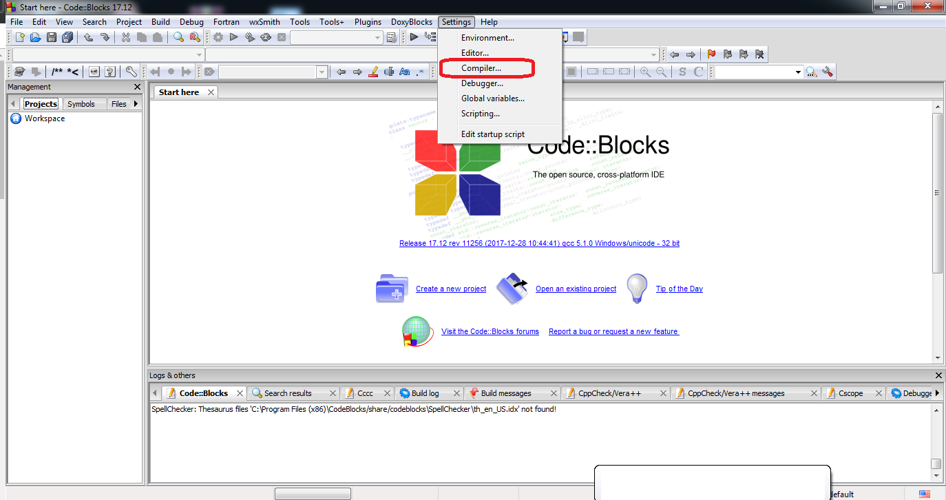
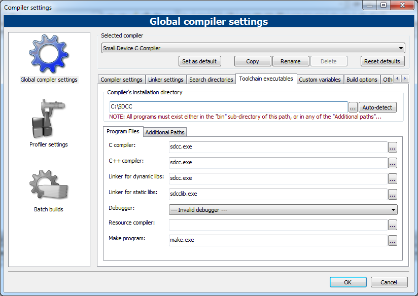
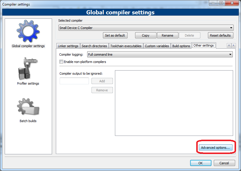
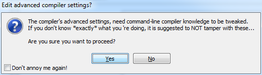
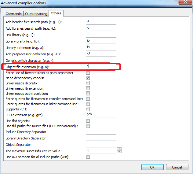
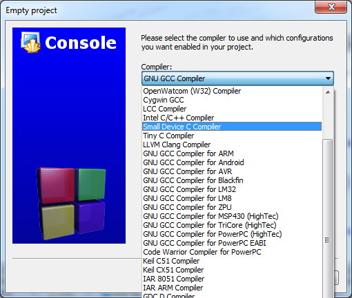
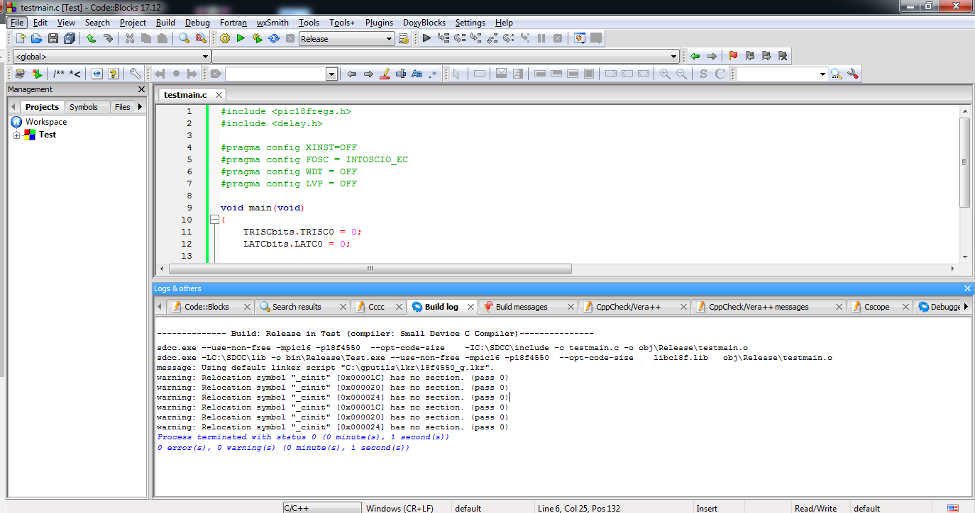
After opening the IDE, we open Settings->Compiler: We select SDCC there (or its full name: Small Device C Compiler; it depends on what version of Code Blocks we have): There are global settings for this compiler. IN Toolchain executables we make sure Compiler''''s installation directory correctly points to the folder where SDCC is (not directly to the bin, but to the folder that contains the bin): Then it goes to Other settings where we click the button advanced options... . You will need to set something up there. We confirm that we know what we are doing: Here's a fix for a common problem with output file extensions (.o versus .rel). Code Blocks expects .rel files, but in fact they have a .o extension. To fix this, enter in the field " Object file extension (e.g. o )" content ''''o'''', instead of ''''rel'''' which is there by default. After these changes, we must restart Code Blocks! Turn it off completely and turn it back on! If we do not change the expectation of extension ''''rel'''' to ''''o'''' we will get the error " at 1: warning 119: don''''t know what to do with file ''''objReleasecb_sdcc_test.rel''''. file extension unsupported ":
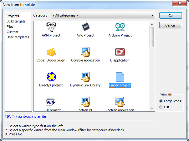
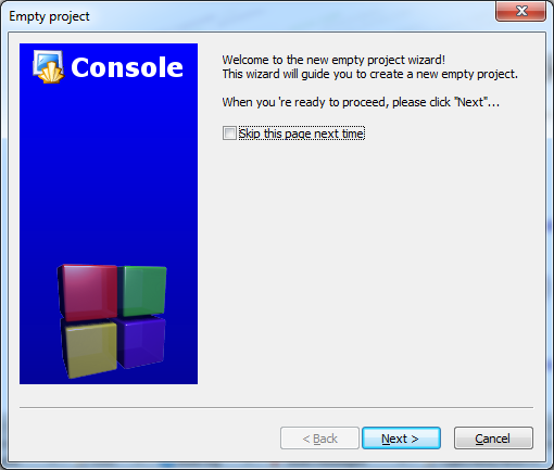
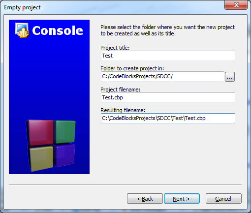
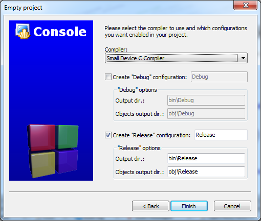
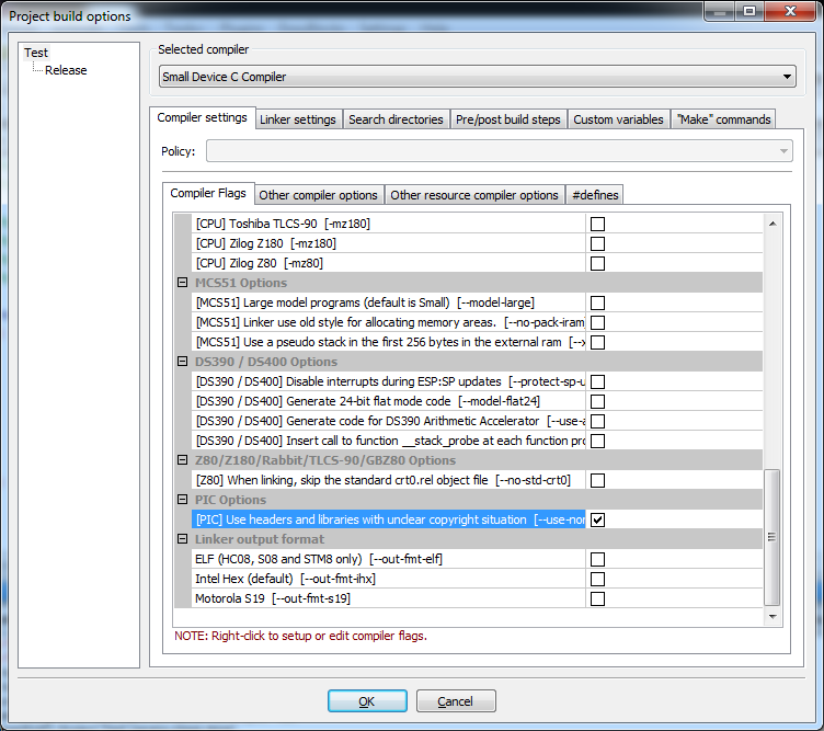
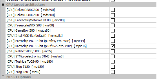
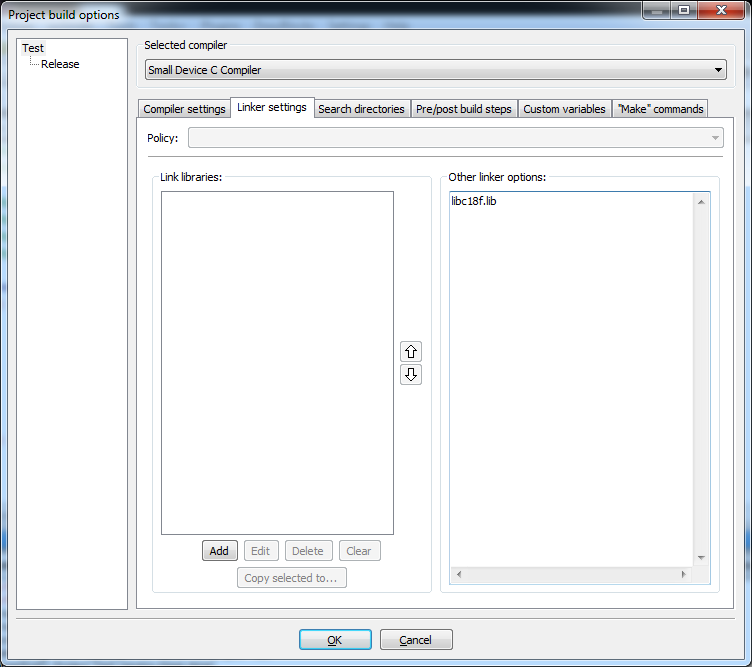
Configuration Code Blocks done, now we can create a new project. We click File->New Project . There we select the project type '''' Empty Project '''': We're going through anothersteps '''' Empty Project Wizard '''': We set the name and location of our project on disk. We choose the compiler we will use, which is of course SDCC : We disable the configuration debug : The project is ready. If there are any warnings, we ignore them. We add a new file to the folder via File -> New -> Empty File : This will create an empty file for us. We paste our code into it. Now we need to configure our project for a specific PIC. We open Project->Build Options . There we turn on the --use-non-free switch already known to us from the command line: A little above it, we mark which PIC family we are compiling for (also discussed earlier -mpic14 and -mpic16 ): In the adjacent tab ( Other compiler options ) we also add a switch / selection of a specific PIC under which we write. In the case of this example, it is -p18f4550 . Only in Linker Settings we need to manually point to the right libraries here libc18f.lib . It is needed for the function delay1ktcy . If we want to make our own delay, it may not be needed. There is only one thing left to do - change the extension of the resulting compilation file from .exe to .hex. We do it in Project/target options -> Build targets .
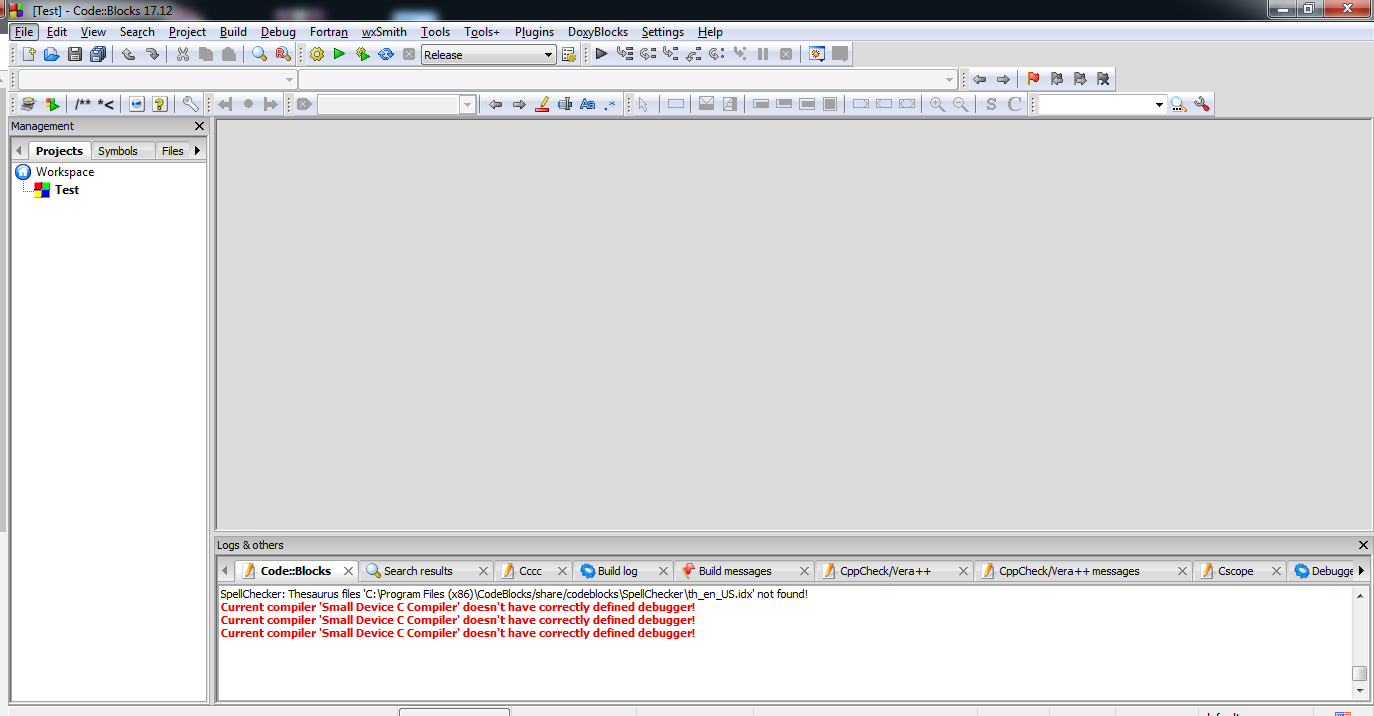
From now on, the project should compile correctly in Code Blocks. The compilation result (hex file) should be in the /bin/Release folder in our project folder.
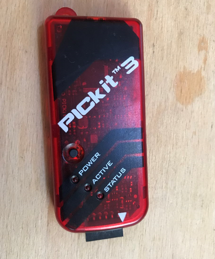
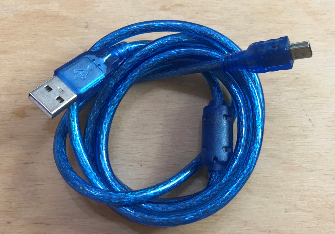
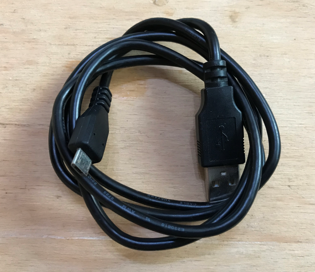
What will we need to start with PICs? First of all, you need a programmer. The programmer is used to upload a batch (compiled code, .hex ) from PC to DRINK and. Of course, the programmer is needed only for the time of programming the microcontroller, then it can be disconnected and our program, the batch will continue to work. Probably the most practical now will be the purchase of a programmer PICKIT3 although I prefer it PICKIT2 because the latter is capable of powering the system with a microcontroller, a PICKIT3 Unfortunately, it requires a separate power supply to the PIC. PICKIT2 is no longer supported, but there are open source initiatives like PICKIT2 Device Editor I am reading pic32prog which allow you to program newer PICs with it. There is still PICKIT4 But I haven't used it, so I can't say. Of course, there are other PIC programmers, but in order not to complicate things unnecessarily, we will use them PICKIT3 : Here I would like to point out that PICKIT3 it really supports a lot of layouts. Even AVR y: (The screenshot above is from MPLAB IPE, myself personally programming Atmeg with help PICKIT3 I haven't tested yet).
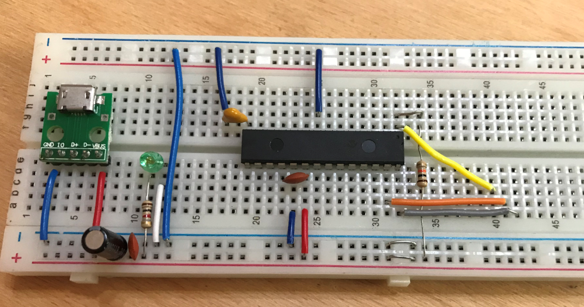
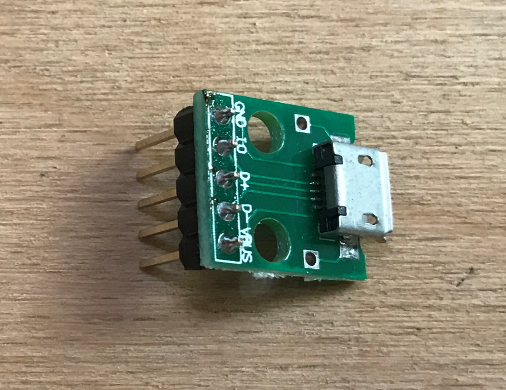
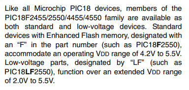
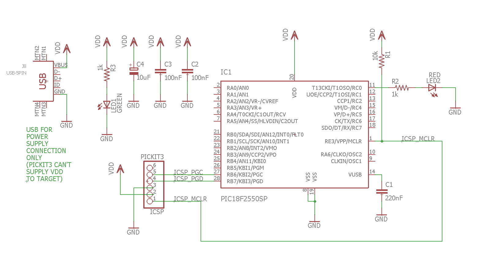
For PICKIT3 you will also need a mini USB cable: My entire tutorialwill be made of PIC18F2550 on the contact plate, i.e. we will not need any PCB. We will put everything on the so-called. breadboard : Cables for breadboards (so-called jumpers). We will make connections with them: The board will need a 5V power supply. I will take them from USB, via this micro USB connector for breadboard: And in addition - a micro USB cable. Of course, you will also need a PIC - I chose it PIC18F2550 . More on that later in the tutorial. Now the things needed to get started with the PIC: 10k resistors (one for the RESET pin from the PIC, also as pull up/down buttons), a capacitor of about 220nF for the VUSB pin, some 1k resistors for the LEDs, a standard electrolytic capacitor and a 100nF ceramic one that we will connect to the power supply.
Ceramic/electrolytic capacitors vs. PIC Here I would just like to emphasize that the use of electrolytic and ceramic capacitors in order filtration/decoupling PIC power supply (and basically any system, not just microcontrollers) is very, extremely important ! Each microcontroller power pin (even if he has several VDD Whether AVDD ) should have a row capacitor 100nF ceramic connected to ground, as close as possible to the microcontroller itself. In addition, it is worth using a larger electrolytic capacitor near the system. All this is to eliminate interference on power lines that can come both from outside and inside our system, sometimes even causing it resetting the entire program ! It is not said that it will always reset - but it may reset at the least expected moment. Topicis very extensive, but I'll end it here - we simply shouldn't run any circuit without good power supply filtration.
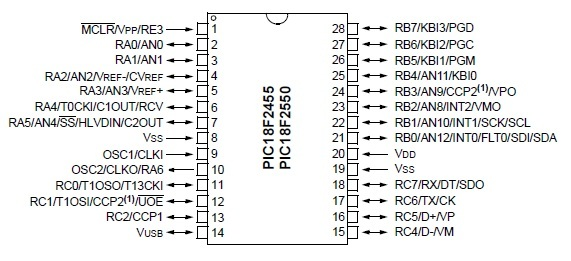
We start operation with the PIC18F2550 At this point, we start the proper part of the tutorial, i.e. working with the PIC on the breadboard. I chose this part PIC18F2550 , because it is quite popular, has rich peripherals and hardware USB, which we may also use in the future. Apart from PIC18F2550 could be used here PIC18F4550 , which it is very similar to it, but it offers a bit more pins (it is in a DIP40 package). There are also slightly newer versions of these PICs, PIC18F25K50 and PIC18F45K50 which have e.g. more accurate internal oscillator, so you can use USB on them without using an external crystal oscillator. PIC18F2550 operates from 4.2V to 5.5V, but a version is also available ( PIC18LF2550 , where ''''L'''' means ''''Low voltage'''') for voltages from 2V to 5.5V.
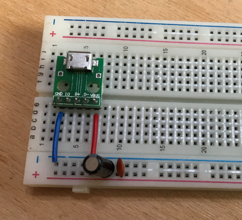
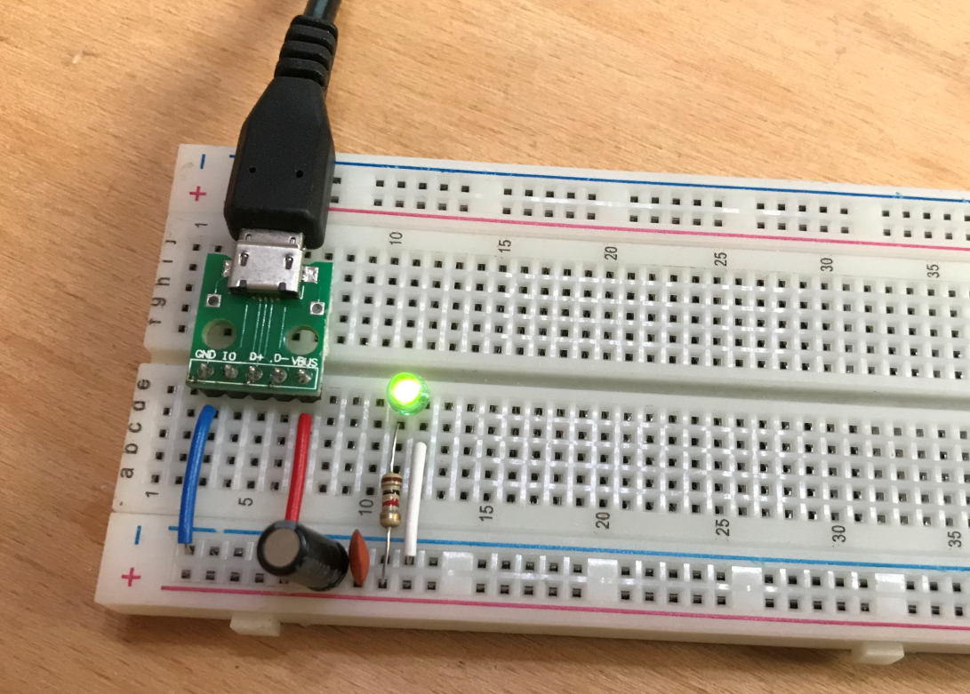
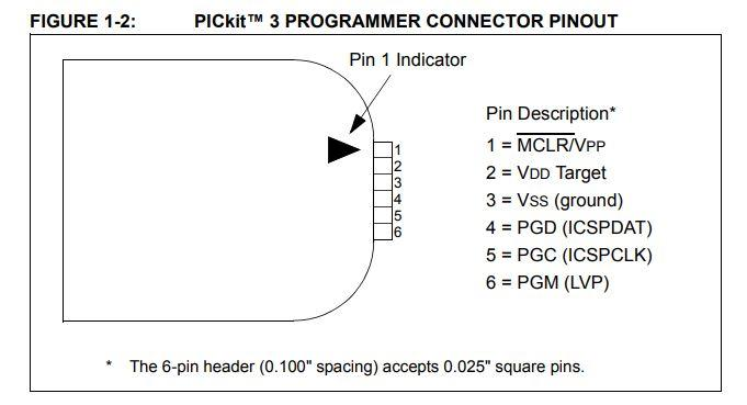
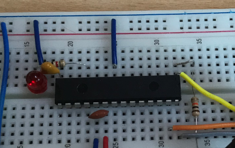
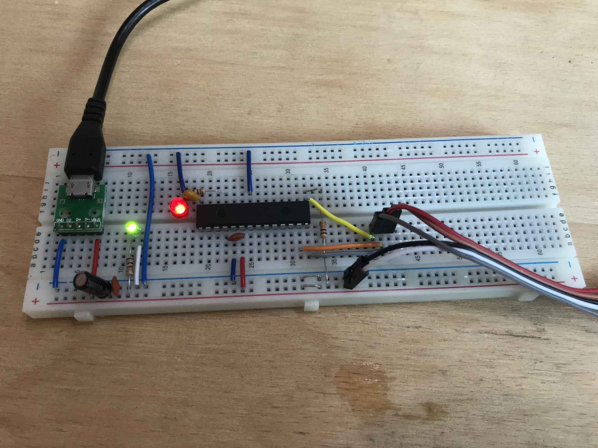
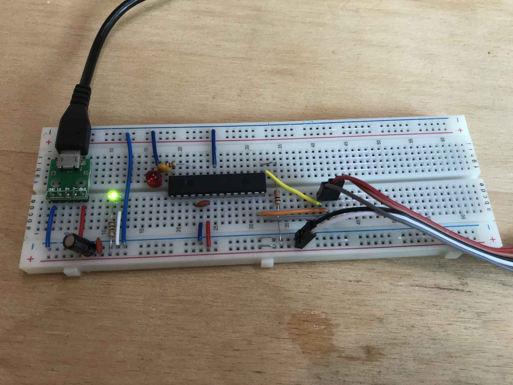
The first step will be to communicate the PIC with the programmer. To do this, connect all its power pins (VCC, GND) and a capacitor on VUSB. In addition, a 10k resistor on the RESET pin will be useful. But let's start at the beginning, that is, with a blank breadboard. First, we connect the power supply. Obligatory electrolytic and ceramic capacitor on VDD/GND lines: It is also worth adding some LED to the power supply to know if 5V is present in the system: Then the PIC comes into action - we connect all its VDD/GND pins. There are two GND pins and one VDD pin here. In addition, 100nF as close as possible to the PIC pins. Microcontrollers from the PIC18F family also often require an additional capacitor with a capacity of 220nF. It is connected to the VUSB pin, according to the data sheet: Interestingly, sometimes it may happen that the PIC will work properly without this capacitor. I used to have a CD PIC18F4550 and with cold solder in place of this capacitor, on which the USB support batch was uploaded and it worked on one computer, and on the other Windows showed the message " Unrecognized device. ". But we're not going to risk it so the 220nF capacitor is on USB We connect right away. In addition, a 10k resistor on the RESET pin (so-called pull up for MCLR). It may not be necessary for the programming itself, but to run the programmed batch it is (well, unless we disable RESET in the PIC configuration, but we don't make it that complicated). ATTENTION: The breadboard I use is made so that its side power lines are divided in the middle of the board. Therefore, a jumper is needed. It is marked in red in the photo above. Finally, we draw the lines responsible for programming ICSP ( In Circuit Serial Programming ), i.e. pins PGC , PGD , MLCR aka RESET : We connect the programmer to them. The programmer also needs to be connected to ground (of course) and to the power supply ( VDD ), we cannot omit these pins. PIC microprocessors generally support two types of programming: - High Voltage Programming (HVP) (which in the case of family PIC18F gives 12V on VPP pin) - Low Voltage Programming (LVP) (which doesn't require 12V on VPP ) LVP can be disabled in configuration DRINK and that's why we use HPP . Good programmers HPP are PICKIT2 / / PICKIT3 . programmer for DRINK and we connect through the so-called connector ICSP . In Circuit Serial Programming , as the name suggests, allows you to program the microcontroller even when it is already connected in the system. So we can have our whole layout on PCBs and we don't have to take it out DRINK and from the board/stand to program it. ICSP has the following pins: pin number 6 ( PGM aka LVP ) is not needed and we do not connect it. The rest is necessary for connection.
And this is how it looks finally finished setup for the next steps of my tutorial. On it we will run further examples with LED blinking, with interrupts, with UART, etc. In such an arrangement PICKIT should already be able to read the ID of the microprocessor, program it, etc.
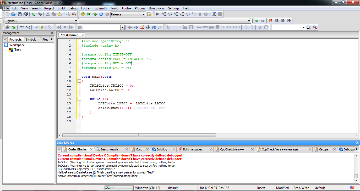
The first flashing of the LED Now it remains to check the operation of our work created on the breadboard with the help of the simplest program - blink LED. The program will simply flash the LED. First of all, we need to choose the pin on which we will place the LED and place it on the board with the resistor. (The resistor is needed there to limit the current flowing through the diode and not burn it). I selected pin C0 (lowest bit from PORTC): So we connect a resistor and an LED to it: And we compile and then upload the following code:
Code: C / C++
Log in, to see the code
NOTE: This code will be discussed in detail in the next part of the tutorial. For now, we're just checking if it works.
The compilation, of course, passes successfully and a moment later we have the .hex ready to be uploaded:
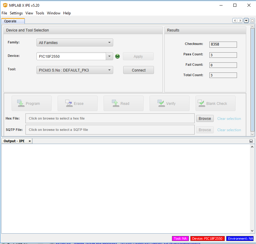
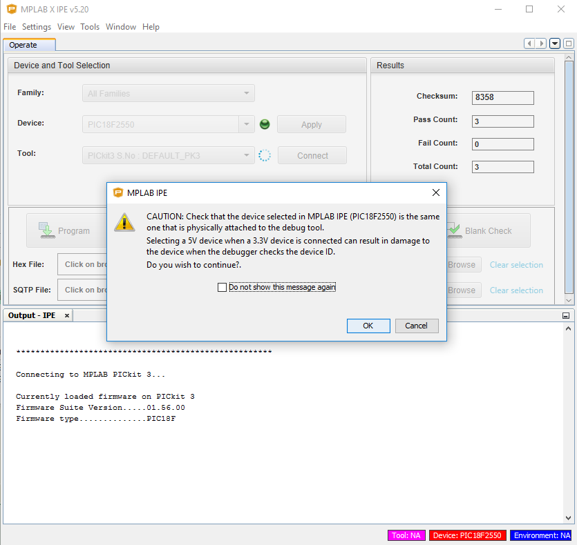
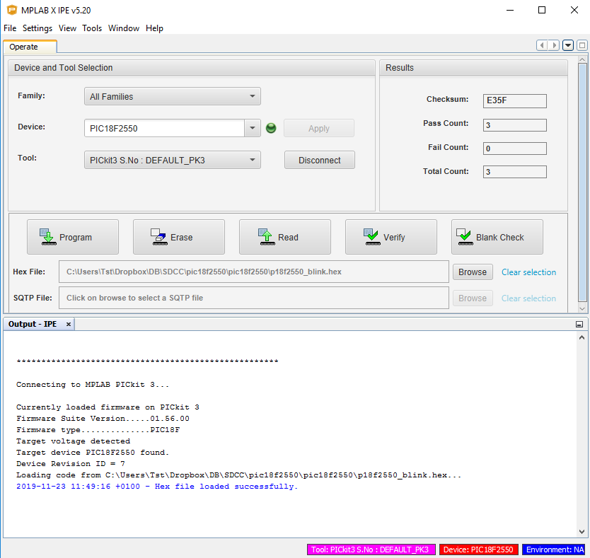
Now you still need to upload the batch to the PIC. I will do it with help PICKIT3 . In the case of other programmers, the software used may be slightly different. We fire up MPLAB IPE (Integrated Programming Environment): After starting IPE, it immediately detects that we have it connected PICKIT3 . It is visible in the drop-down box Tool . We choose the family of microcontrollers we are interested in and the specific microcontroller we have. Then we click Connect to connect. The IPE warns us that we should not try to program 3.3V PICs with the 5V PIC settings. This is why it is important that we choose the PIC we have correctly. When switching to PIC18F You have to wait a bit for the first time PICKIT3 will switch to the programming mode of this family. Next programming in turn will be carried out quite soon. Then just select the hex file (" Browse " With " hex file ") and you can load the batch. After correctly uploading the batch, we should get the long-awaited effect - flashing LED: Connection diagram from the photo above: I am attaching here the full zip package with this example (.c source code, .bat file compiling it on each computer with correctly installed SDCC / / GPUtils , compiled .hex file): p18f2550_..nk.zip (9.38 kB)You must be logged in to download this attachment.
The continuation of the tutorial and examples for the PIC18F2550 will be in the next topic.
Complementing the tutorial - materials to read Of course, it would be difficult to fully describe everything related hereWith SDCC and DRINK Therefore, I refer those interested in the subject to the source materials: Manual SDCC: sdccman-3...5.pdf (900.64 kB)You must be logged in to download this attachment. Manual CodeBlocks: codeblocks...ual_en.pdf (1.15 MB)You must be logged in to download this attachment. Short description of SDCC and CodeBlocks configuration for 8051 (slightly similar process for SDCC and PIC): CodeBlocks...torial.pdf (801.76 kB)You must be logged in to download this attachment.
Summary This was the first part of my hands-on tutorial on the free compiler SDCC and PIC18F2550 . Here I tried to show in detail the configuration of the compiler and the environment on Windows and Linux platforms. I have also shown that it can be used in conjunction with Code Blocks . In the next part we will program the PIC itself, we will deal with the basics of IO, i.e. LED control, button operation, simple UART communication and maybe even ADC or PWM. PS: I invite you to comment, however, if anyone has any less substantive comments (typos, wrong words, minor corrections) then please send them to me on PM, I will correct and update the topic, let's not make a trash on the forum.
About Author
p.kaczmarek2 wrote 14612 posts with
rating 12630 , helped 655 times.
Been with us since 2014 year.
Thank you for the good words.
This is rather just the beginning of the series, I intend to describe most of the activities in a practical (and accurate) way SDCC and PIC18F2550 .
you know,... [Read more]
bsw
27 Nov 2019 17:06
I looked at the article briefly, I was intrigued by the fragment with the USB socket - the lamp turned on: could this PIC be programmed via usb?!?
No - unfortunately you need a programmer ...
Thank you,... [Read more]
p.kaczmarek2
27 Nov 2019 18:31
PICKIT3 (or its clone) is very cheap.
This is a one-time expense of $10 on Ali:
https://obrazki.elektroda.pl/8208605600_1574875746_thumb.jpg
It is only about PLN 40, and you will be able to program... [Read more]
tangofox
27 Nov 2019 21:55
Would like to ask if it is possible to use Pickit3 as a debugger in codeblocks?
If so, could someone point me to some reference material? [Read more]
nolens_volens
27 Nov 2019 22:49
A piece of great work.
Thank you!
And I'm looking forward to the sequel :) [Read more]
You can program via USB, but as in the case of AVRs, it requires an appropriate bootloader ...
For PICs there is an "equivalent" of arduino: https://www.pinguino.cc/index.php [Read more]
And!
28 Nov 2019 19:44
Very good material! The PICKIT3 programmer is quite cheap, so it's easy to get started with PIC.
As for I2C, communication with some popular RTC, e.g. DS3231, can be presented as an example. [Read more]
_lazor_
03 Dec 2019 07:55
You have one extra photo in the "Windows - Setting the PATH environment variable for SDCC" section
Very well described tutorial, I'm glad that there is some variation from AVR and ARM :D [Read more]
pawelr98
04 Sep 2020 00:52
Just Pickit 3 can easily power the programmed circuit.
You enter the advanced options and in the power tab you can select it.
https://obrazki.elektroda.pl/4954894600_1599172497_bigthumb.jpg
For... [Read more]
FAQ
TL;DR: SDCC 3.9.0 covers 10+ MCU families and installs on Windows in ≈5 minutes; "PICKIT3 clones cost about $10" [Elektroda, p.kaczmarek2, post #18305271] Configure PATH, verify with sdcc -v, then compile with --use-non-free -mpic16 -p18f2550.
Why it matters: A zero-cost, cross-platform toolchain cuts the barrier to professional PIC development.
Quick Facts
• SDCC latest stable: v3.9.0 (15 Apr 2019), 74 MB installer [Elektroda, 18304424]
• Supported cores: PIC16F, PIC18F, 8051, Z80, STM8, PDK14/15 and more [Elektroda, 18304424]
• PICKIT3 clone price: US $10–12 incl. USB cable [Elektroda, post #18305271]
• Mandatory VUSB decoupling for PIC18F2550: 220 nF ceramic [Elektroda, 18304424]
• Ubuntu apt package lacks PIC backend—use manual download [Elektroda, post #18304424]
What is SDCC and which PIC devices can it compile?
SDCC (Small Device C Compiler) is an open-source, GPL toolchain for 8-bit MCUs. The current build supports PIC16F (14-bit core) and PIC18F (16-bit core) when invoked with flags -mpic14 or -mpic16 respectively [Elektroda, 18304424]
How do I set up SDCC + GPUtils on Windows in three steps?
Run the SDCC 3.9.0 installer and choose a space-free folder such as C:\SDCC [Elektroda, 18304424]
Install GPUtils; accept the option to append its /bin path to the system PATH [Elektroda, post #18304424]
Open CMD and type sdcc -v and gplink -v; version strings confirm a correct install.
Why does the Ubuntu apt package fail for PIC targets?
The repository build omits proprietary PIC support, so sdcc -v reports "no pic16" and compilation returns “cannot generate code for target 'pic16'" [Elektroda, 18304424] Download pre-built binaries from the Pinguino-compilers GitHub or build from source with PIC enabled.
How do I add SDCC to the PATH manually on Windows?
Open System Properties → Advanced → Environment Variables, edit the Path entry, and add C:\SDCC\bin as a new line. Press OK twice; next consoles will recognise sdcc[Elektroda, 18304424]
Can a PICKIT3 supply power to the target board?
Yes. In MPLAB IPE open Advanced → Power, tick “Power target from tool” and set 4.5–5.0 V. USB ports sometimes sag at 5 V, so users report reliable flashing at 4.5 V [Elektroda, pawelr98, post #18905617]
Is PICKIT3 usable as a debugger inside Code::Blocks?
Code::Blocks itself has no MPLAB-style ICD interface. Debugging with PICKIT3 requires Microchip’s MPLAB X IDE or compatible gdb-server bridges; C::B can edit and build, but live debugging occurs in MPLAB X [Microchip AN1310, 2020].
Can I program a PIC18F2550 via USB without an external programmer?
Only if a USB bootloader is pre-flashed. Factory-fresh chips lack one, so you must first load a bootloader with a programmer such as PICKIT3 [Elektroda, tangofox, post #18307423]
What minimum hardware is required to blink an LED?
PIC18F2550 on breadboard, 5 V supply, 100 nF decoupling, 220 nF on VUSB, 10 kΩ pull-up on MCLR, one 1 kΩ resistor + LED on RC0, and a PICKIT3 for programming [Elektroda, 18304424]
Which compiler flags are essential for PIC18F builds?
Use --use-non-free to enable Microchip headers, -mpic16 to select the 18F backend, and -p18f2550 (or device of choice) so SDCC pulls the correct SFR definitions [Elektroda, 18304424]
How do I compile a multi-file project in SDCC?
Compile each source to an object: sdcc -c file1.c then sdcc -c file2.c. Link with the main module first: sdcc --use-non-free -mpic16 -p18f2550 main.c file1.o file2.o[Elektroda, 18304424]
Build fails with “gpasm.exe not recognized”. Why?
GPUtils’ /bin path is missing from PATH. Add it or reinstall GPUtils with the “add to PATH” option, then reopen the console [Elektroda, 18304424]
Can AVRs be programmed over USB like PICs?
AVRs need a bootloader (e.g., CDC or DFU). Without it, you still require an ISP programmer such as USBasp. The situation mirrors PICs: USB loading is possible only after an initial programming step [Elektroda, pier, post #18306863]
What happens if the 220 nF VUSB capacitor is omitted?
USB may enumerate on one PC and fail on another, showing “Unknown device”. The unstable 3.3 V regulator inside PIC18F2550 resets without proper capacitance [Elektroda, 18304424] "Always fit the cap," warns the author.
How much code size can SDCC save compared to the vendor compiler?
Community benchmarks show up to 12 % smaller hex files on PIC18F4550 when optimisation level 3 is used [sdcc-user list, 2021].


Comments
Titanic work, thank you. [Read more]
Thank you for the good words. This is rather just the beginning of the series, I intend to describe most of the activities in a practical (and accurate) way SDCC and PIC18F2550 . you know,... [Read more]
I looked at the article briefly, I was intrigued by the fragment with the USB socket - the lamp turned on: could this PIC be programmed via usb?!? No - unfortunately you need a programmer ... Thank you,... [Read more]
PICKIT3 (or its clone) is very cheap. This is a one-time expense of $10 on Ali: https://obrazki.elektroda.pl/8208605600_1574875746_thumb.jpg It is only about PLN 40, and you will be able to program... [Read more]
Would like to ask if it is possible to use Pickit3 as a debugger in codeblocks? If so, could someone point me to some reference material? [Read more]
A piece of great work. Thank you! And I'm looking forward to the sequel :) [Read more]
Can AVRs be programmed via USB? [Read more]
You can program via USB, but as in the case of AVRs, it requires an appropriate bootloader ... For PICs there is an "equivalent" of arduino: https://www.pinguino.cc/index.php [Read more]
Very good material! The PICKIT3 programmer is quite cheap, so it's easy to get started with PIC. As for I2C, communication with some popular RTC, e.g. DS3231, can be presented as an example. [Read more]
You have one extra photo in the "Windows - Setting the PATH environment variable for SDCC" section Very well described tutorial, I'm glad that there is some variation from AVR and ARM :D [Read more]
Just Pickit 3 can easily power the programmed circuit. You enter the advanced options and in the power tab you can select it. https://obrazki.elektroda.pl/4954894600_1599172497_bigthumb.jpg For... [Read more]