How to check the electromagnetic relay? One way
Some time ago there were several articles on our forum about basic issues, min. <br/span> Some time ago, there were several articles on basic issues in our forum, including "How to check a fuse?", and although several people thought that the subject was too obvious, I would argue that .... maybe not quite. I believe that people, even those working in the industry, often get "lectured" on this very type of measurement.... My article today will focus specifically on the relay and how not to be fooled yourself when checking it. The situation was excellent because I had just such a faulty component. Nothing was simulated here. So I thought I would present and describe the situation.
Of course, I am talking about electromagnetic relays, which are widely used in a variety of electrical, electronic and automotive equipment. It should be remembered, however, that there are also other designs, but not about that now.
As for the basics, principles of operation, markings, symbols - I refer to the literature, the Internet or even our forum:
https://www.elektroda.pl/rtvforum/topic3102772.html
Here we focus only on how to check such an element.
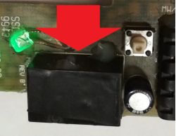
And then there is our defective hero of the episode. A small relay in a black housing. Mounted on a PCB, this is the module from the car. Pressing the momentary tact switch visible on the right switches on the relay's operating contact, which applies 12V to the module's output. Another press switches it off. I deliberately do not show the whole circuit, how it is controlled etc. as I want to show, on this particular example, the operation, behaviour of the damaged relay itself . The green LED does not have any meaning here, please do not be confused by it .
.
.
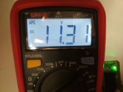
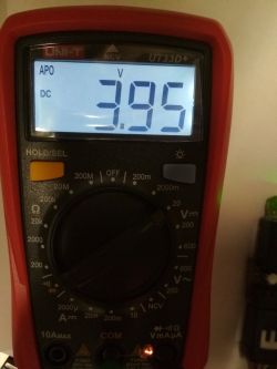
We start the test, module driven, multimeter connected at the output, like a receiver. When switched on, full voltage appears, as if everything should be working. Voltage a little below 12V because the whole circuit was powered from just such a voltage.
.
Well, maybe a more expensive multimeter will detect some anomalies? Check out the video to see what it looks like with the Sanwa.
Everything looks as it should all the time...
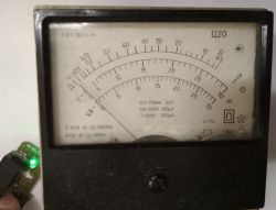
How about an old analogue multimeter?
.
None of the instruments showed any abnormalities....
LED with resistor? In the video below, the green LED on the left connected in series with a resistor, plugged into the output, as a receiver.
.
Nothing of the methods so far has caused the relay to fail. And let me remind you that it is faulty! .
.
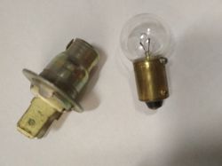
And an ordinary 12V low-power bulb?
.
In this case finally something starts to happen, The output voltage drops, it does not reach 12V, the bulb does not light up completely, it dims.
.
.
Only the last test showed the damage. The working contacts of the relay may be responsible for this symptom, which qualifies the relay in its entirety for replacement. This article was intended to show that sometimes just checking with a multimeter or suggesting the LED indication is not always correct. In a case like this, the test must be performed under load. Traditional incandescent lamps with a voltage and wattage adapted to the component under test are ideal for this purpose.Sometimes flickering, dimming, incorrect operation of the receiver can be observed immediately. The use of too high a load can only do harm here; too low a load will not always reveal the fault. Finally, I would like to remind you that we were operating at around 12V here, so you can afford such experiments; if you are checking components at e.g. 230V, do not do such tests for safety reasons!
Of course, I am talking about electromagnetic relays, which are widely used in a variety of electrical, electronic and automotive equipment. It should be remembered, however, that there are also other designs, but not about that now.
As for the basics, principles of operation, markings, symbols - I refer to the literature, the Internet or even our forum:
https://www.elektroda.pl/rtvforum/topic3102772.html
Here we focus only on how to check such an element.
And then there is our defective hero of the episode. A small relay in a black housing. Mounted on a PCB, this is the module from the car. Pressing the momentary tact switch visible on the right switches on the relay's operating contact, which applies 12V to the module's output. Another press switches it off. I deliberately do not show the whole circuit, how it is controlled etc. as I want to show, on this particular example, the operation, behaviour of the damaged relay itself . The green LED does not have any meaning here, please do not be confused by it
.
We start the test, module driven, multimeter connected at the output, like a receiver. When switched on, full voltage appears, as if everything should be working. Voltage a little below 12V because the whole circuit was powered from just such a voltage.
.
Well, maybe a more expensive multimeter will detect some anomalies? Check out the video to see what it looks like with the Sanwa.
Everything looks as it should all the time...
How about an old analogue multimeter?
None of the instruments showed any abnormalities....
LED with resistor? In the video below, the green LED on the left connected in series with a resistor, plugged into the output, as a receiver.
Nothing of the methods so far has caused the relay to fail. And let me remind you that it is faulty!
And an ordinary 12V low-power bulb?
.
In this case finally something starts to happen, The output voltage drops, it does not reach 12V, the bulb does not light up completely, it dims.
.
Only the last test showed the damage. The working contacts of the relay may be responsible for this symptom, which qualifies the relay in its entirety for replacement. This article was intended to show that sometimes just checking with a multimeter or suggesting the LED indication is not always correct. In a case like this, the test must be performed under load. Traditional incandescent lamps with a voltage and wattage adapted to the component under test are ideal for this purpose.Sometimes flickering, dimming, incorrect operation of the receiver can be observed immediately. The use of too high a load can only do harm here; too low a load will not always reveal the fault. Finally, I would like to remind you that we were operating at around 12V here, so you can afford such experiments; if you are checking components at e.g. 230V, do not do such tests for safety reasons!


Comments
And measuring the contact resistance with an ohmmeter? [Read more]
Here, it is a situation where the working contacts of the relay form an electrical contact sufficient for small currents but, due to a manufacturing defect (or mechanical damage or corrosion, etc.), at... [Read more]
In measuring automotive installations, I learned a long time ago to test the voltage (especially of the power supply) under load or with the module sensor attached (inserting needles from the back of the... [Read more]
. An ohmmeter causes a small current to flow so it could also fail at such a fault. It doesn't put a load on our relay contacts. How many times has something that appeared to work on an ohmmeter failed... [Read more]
Specialised testers such as Testboy are designed for this purpose. They have several test options, including higher current. [Read more]
And in addition, this is only the beginning of the types of relay failures. Almost nothing can be detected with a multimeter. It is a pity that the author of the post did not show how much the contact... [Read more]
This subject has already been discussed in the past, we had one at work, but it was even 4 NO and NC contacts and the indicator was the light bulbs. Hundreds of different relays were checked during the... [Read more]
Experienced electricians have long since established that voltmeters (~multimeter) with a high input resistance are not suitable for testing current circuits. Electric installations exposed to moisture... [Read more]
Two incandescent lamps of the same wattage connected in series are better. At 230 volts they will also light up (less brightly, of course), but there is no risk of them blowing up when connected to two... [Read more]
Don't hint! Let them think. ;-) [Read more]
As mentioned above , I would start by measuring the coil resistance (for continuity) before applying voltage, and measuring the contact resistance after applying voltage to the coil . [Read more]
The bulb should always be the classic for checking current circuits, good current rise, great limiting at the same time, and also visual inspection. [Read more]
. . It's a pity that you didn't check it, maybe it would have turned out that even a meter for a dozen or so zloty would have been able to cope, and the whole article about how intelligent you are and... [Read more]
Yes, and no. I just had a problem where relays were switching 4 circuits, some of which were switching some small but nonetheless loads, and some of which were providing a signal to the controller (i.e.... [Read more]
Hello, I had a similar case but with a power amplifier i.e. every now and then the volume in one channel would drop and there was a slight crackle. I replaced the input potentiometer, checked all the solders... [Read more]
Similar situations happen in old cars (yes more than 30 years old). The insulation in the wires loses elasticity and they like to break most often at the connectors. In this case, the multimeter will not... [Read more]
Sometimes even the plugs themselves make bad contact. A common problem in VAG throttle plugs. Apparently everything is ok and the contact on the connector is poor. The same applies to the wires, which... [Read more]
A few words of explanation... In writing this article I can now see that I made a small mistake. I focused on one case of mine that happened to me during a repair. Because I wasn't set on writing the... [Read more]
. That's what you've done in this video. To improve it, use a 1A current source instead of an incandescent bulb. [Read more]