FAQ
TL;DR: Want ESP8266/ESP32 to know if a 12 V relay switched? Sense the driver’s collector with a 10 kΩ pull‑up to 3.3 V; "The signal will be in negation." [Elektroda, krzbor, post #19019675]
Why it matters: You need a reliable GPIO read even when another circuit drives the same relay; this FAQ is for ESP8266/ESP32 makers wanting safe, accurate relay state monitoring.
Quick Facts
- ESP8266/ESP32 GPIOs are 3.3 V logic; design dividers or pull‑ups accordingly. [Elektroda, khoam, post #19014867]
- "The only certain information about its switching is the state of the contacts." [Elektroda, jozgo, post #19014825]
- Monitoring coil voltage does not prove the contacts moved. [Elektroda, khoam, post #19014816]
- Add an optocoupler if you need galvanic isolation from the MCU. [Elektroda, jozgo, post #19014920]
- You can sense 230 V contact state using a mains zero‑cross detector circuit. [Elektroda, krzysiek_krm, post #19015042]
How can I reliably detect if my 12 V relay actually switched?
Sense the relay’s contacts, not just the coil or drive signal. Any unused contact can serve as a status output. As one expert put it, "The only certain information about its switching is the state of the contacts." This directly reflects mechanical closure. [Elektroda, jozgo, post #19014825]
Can I just monitor the 12 V coil to know the relay status?
No. Coil voltage or current does not guarantee contact movement. Edge case: the coil can energize while the contacts fail to change state. As noted, "This will 100% not mean that the contacts have switched on or off." Rely on contacts or a properly derived sense node. [Elektroda, khoam, post #19014816]
What�s the easiest way to read relay status on ESP8266/ESP32 without touching 230 V?
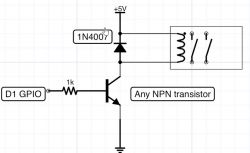
Tap the relay driver�s collector node and pull it up to 3.3 V through ~10 k�a. Feed that node to a free GPIO. This works when the ESP and relay driver share ground and provides a clean logic signal. Note the signal is inverted relative to coil power. [Elektroda, krzbor, post #19019675]
How do I wire the collector-sense method to an ESP GPIO?
- Ensure common ground between the relay driver and ESP supply.
- Add a 10 k�a resistor from the flyback diode�s anode node (collector side) to 3.3 V.
- Connect that same anode node to a free ESP GPIO; expect inverted logic. [Elektroda, krzbor, post #19019675]
Is the collector-sense logic inverted?
Yes. When the coil is energized, the collector node goes low, so the GPIO reads low. When the coil is off, the pull‑up drives the node high. "The signal will be in negation." Adjust your firmware logic accordingly. [Elektroda, krzbor, post #19019675]
Do I need galvanic isolation for relay status sensing?
Use an optocoupler if you need isolation between the relay circuit and the ESP. It protects the MCU from transients and different ground potentials. As advised, "For separation, you can insert an optocoupler." This is preferred in noisy or high‑voltage environments. [Elektroda, jozgo, post #19014920]
How can I detect 230 V on the relay contacts safely?
Use a mains zero‑cross detector or similar high‑impedance sensing circuit. This indicates whether 230 V is present on the switched contact without loading the line. It avoids relying on coil status and directly measures the AC side condition. [Elektroda, krzysiek_krm, post #19015042]
Which ESP8266/ESP32 pins can I use as inputs for status sensing?
Use any GPIO that supports input mode on your ESP8266 or ESP32. Choose pins that fit your board�s boot requirements and your firmware design. Refer to a pinout guide for selection details. [Elektroda, khoam, post #19014772]
Can I drop a higher node voltage to a logic-level input with a zener + resistor?
Yes. A simple zener diode with a series resistor can clamp the sense node to a lower voltage. For example, down to about 5 V at the node, yielding an inverted signal referenced to the driver. This helps protect the input stage. [Elektroda, jozgo, post #19014862]
What voltage should an ESP GPIO see as HIGH?
Target 3.3 V logic levels for ESP8266/ESP32 inputs. As noted, "Specifically to 3V3, as this is the ESP." Avoid 5 V direct connections without proper level shifting or clamping. This protects the microcontroller inputs. [Elektroda, khoam, post #19014867]
Can I reuse an unused relay contact purely for feedback?
Yes. Any contact not used to switch the load can serve as a feedback signal path. Wire it to a suitable low‑voltage sensing circuit or isolation stage, then into a GPIO. This mirrors industrial auxiliary contact practice. [Elektroda, jozgo, post #19014779]
Why not read the D1 drive signal if another circuit also switches the relay?
Because the control signal you drive won�t reflect external activations. As the OP states, "the relay can also be switched on by another circuit (not ESP)." You need contact sensing or a shared node that changes for all drivers. [Elektroda, faber, post #19014759]
Will a 10 k�a pull-up work for collector sensing, or should I pick another value?
10 k�a to the ESP�s 3.3 V rail works well for this method. It limits current, keeps the node stable, and produces the expected inverted logic. This value is commonly suggested for the collector‑sense technique described. [Elektroda, krzbor, post #19019675]
 .
.
 .
.


