






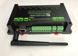
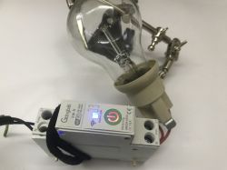

I would like to present my smart building project. The whole system is based on Raspberry PI and the control of all devices is done wirelessly using the RFM12b module.
The graphical interface can be tested at: http://student.agh.edu.pl/~dkalicki/house_control/indexObj.html
this is a rather old version and the latest one is on Rpi. This is not the page that is plugged into the system.
The transmission sent out into the ether includes AES encryption with a counter, so the possibility of someone hacking into the system from the outside is limited.
All devices are based on Atmega + RFM12b module. In terms of range I have no problem controlling a device in another room, but the maximum distance the sensors operate at I do not know.
One of the main considerations was the small cost of the devices, which is why I chose the RFM12b module, although I am considering changing the radio module to ZigBee the price will be similar but it will require making my own PCB module.
As you will see in the videos below, I have not yet calibrated the sensors and interfaces so indications of over 100% should not be surprising, as well as the reverse indication of the bulb on the interface.
I apologise of course for the quality of the videos but I don't have a better camera.
The system consists of devices:
1. Lighting controller.
Allows you to switch the lighting on and off, and for standard incandescent and probably halogen bulbs to change their brightness. It also allows you to switch a device (with a small current consumption of up to 1A) on and off from the mains voltage. This is a popular triac-based lighting controller circuit. For this circuit I am going to include a power consumption counting module built on an ADE7755.
http://www.youtube.com/watch?v=pB87S6wcYbE
2. Ambient sensor:
Informs about the ambient temperature and lighting. In addition, it includes a CO sensor and a motion sensor. And in the future a humidity and pressure sensor.
http://www.youtube.com/watch?v=nTM7caZRrJc
3. Soil moisture sensor for plants
I'm having trouble calibrating this sensor so it will probably present information on a scale of low moisture, medium, high or something like that.
http://www.youtube.com/watch?v=D4PRhTfOzoU
4. A circuit to control a motor for a garage door.
A circuit to control a DC motor, and includes leads for limiters and a control button. The circuit is also suitable for controlling roller shutters.
5. Radio remote control
It can be easily connected to any device controlled by the system, using the www interface.
http://www.youtube.com/watch?v=AXeoLLFm0DM
6. TV remote control
Allows you to control your TV from a computer or mobile phone (access via the website).
http://www.youtube.com/watch?v=SsZKNVUrXbY
In addition, I am working on a simple thermostat that will control the valve on the radiator.
I will try to post a more detailed description of how it works and the schematics as soon as I find the time to write it up.
I don't think the project deserves a DIY post due to the small shortcomings of the software (sensor calibration) so I'm posting it here.
The graphical interface can be tested at: http://student.agh.edu.pl/~dkalicki/house_control/indexObj.html
this is a rather old version and the latest one is on Rpi. This is not the page that is plugged into the system.
The transmission sent out into the ether includes AES encryption with a counter, so the possibility of someone hacking into the system from the outside is limited.
All devices are based on Atmega + RFM12b module. In terms of range I have no problem controlling a device in another room, but the maximum distance the sensors operate at I do not know.
One of the main considerations was the small cost of the devices, which is why I chose the RFM12b module, although I am considering changing the radio module to ZigBee the price will be similar but it will require making my own PCB module.
As you will see in the videos below, I have not yet calibrated the sensors and interfaces so indications of over 100% should not be surprising, as well as the reverse indication of the bulb on the interface.
I apologise of course for the quality of the videos but I don't have a better camera.
The system consists of devices:
1. Lighting controller.
Allows you to switch the lighting on and off, and for standard incandescent and probably halogen bulbs to change their brightness. It also allows you to switch a device (with a small current consumption of up to 1A) on and off from the mains voltage. This is a popular triac-based lighting controller circuit. For this circuit I am going to include a power consumption counting module built on an ADE7755.
http://www.youtube.com/watch?v=pB87S6wcYbE
2. Ambient sensor:
Informs about the ambient temperature and lighting. In addition, it includes a CO sensor and a motion sensor. And in the future a humidity and pressure sensor.
http://www.youtube.com/watch?v=nTM7caZRrJc
3. Soil moisture sensor for plants
I'm having trouble calibrating this sensor so it will probably present information on a scale of low moisture, medium, high or something like that.
http://www.youtube.com/watch?v=D4PRhTfOzoU
4. A circuit to control a motor for a garage door.
A circuit to control a DC motor, and includes leads for limiters and a control button. The circuit is also suitable for controlling roller shutters.
5. Radio remote control
It can be easily connected to any device controlled by the system, using the www interface.
http://www.youtube.com/watch?v=AXeoLLFm0DM
6. TV remote control
Allows you to control your TV from a computer or mobile phone (access via the website).
http://www.youtube.com/watch?v=SsZKNVUrXbY
In addition, I am working on a simple thermostat that will control the valve on the radiator.
I will try to post a more detailed description of how it works and the schematics as soon as I find the time to write it up.
I don't think the project deserves a DIY post due to the small shortcomings of the software (sensor calibration) so I'm posting it here.

