






English Translation (for Elektroda forum, professional hardware technical writing)
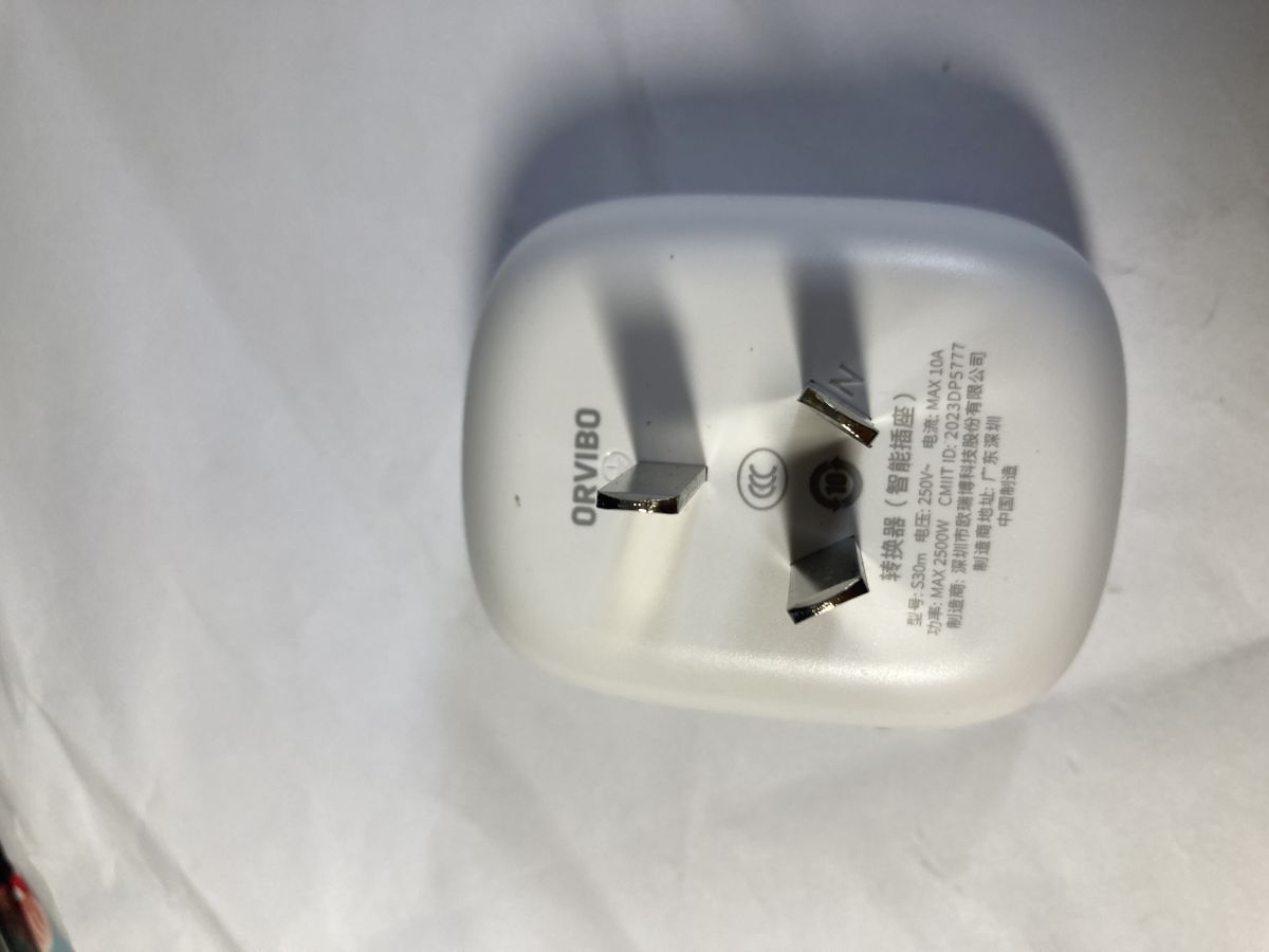
I bought several ORVIBO S30M smart sockets customized for China Mobile Hejiaqin on Xianyu second-hand marketplace, planning to flash OpenBeken firmware onto them. However, I cannot enter bootloader flashing mode no matter what methods I try. I’ve consulted AI tools and learned this batch may be carrier-customized hardware locked against third-party flashing. I’m asking experienced community members for troubleshooting guidance.
Prerequisite Information
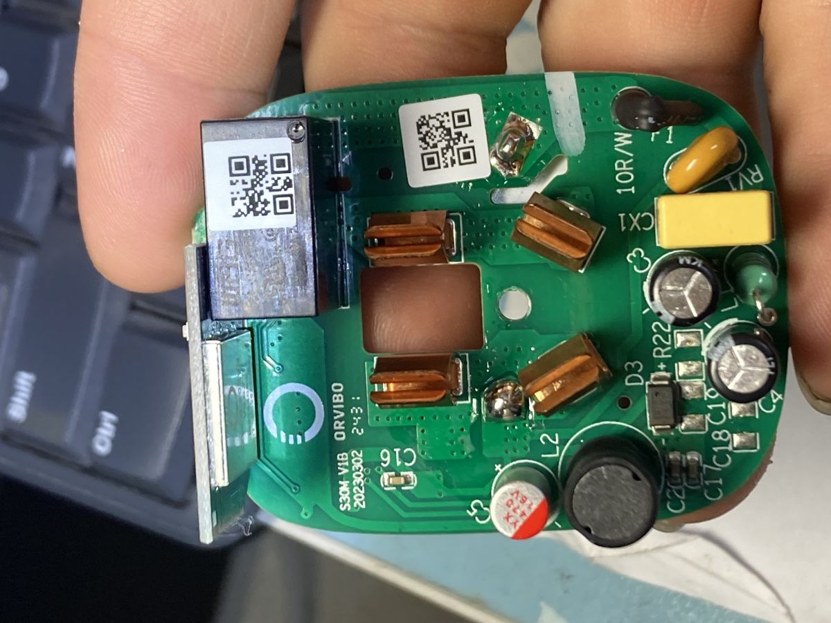
Model: ORVIBO S30M-V1B, mass-produced in 2023, exclusive customized version for China Mobile Hejiaqin
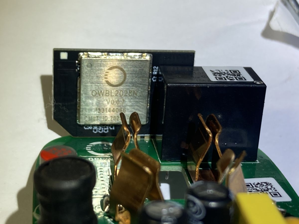
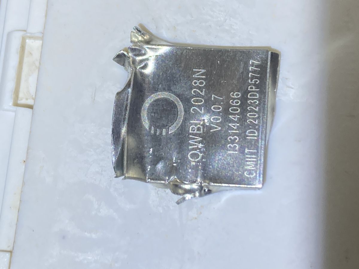
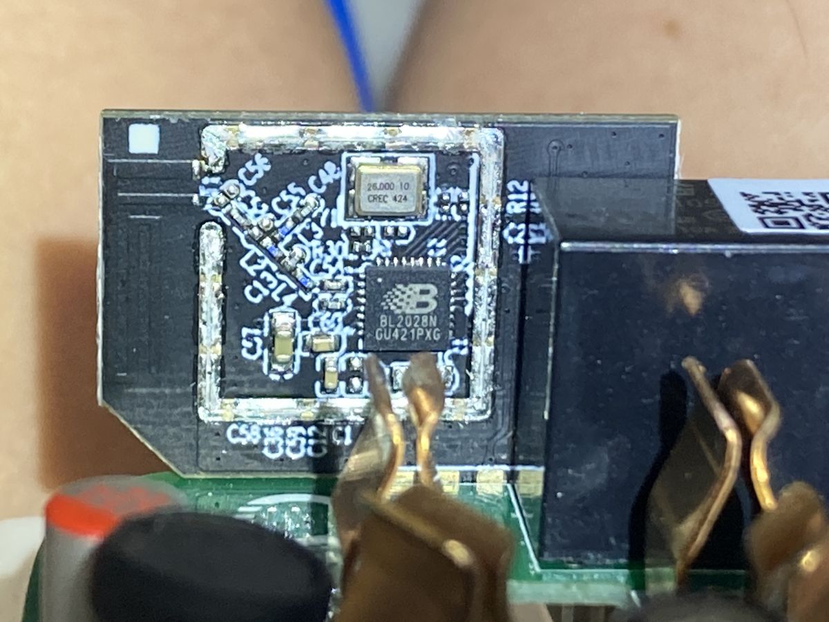
Onboard chip: Shanghai Beken BL2028N (equivalent to BK7231N, module model OWBL2028N)
BL2028N is a rebranded variant of BK7231N. They share identical hardware specifications and instruction sets, so third-party firmware like OpenBeken is fully compatible in theory.
Flashing Tools Used
1. BK7231Flasher.exe
2. CH340 USB-to-TTL serial adapter
Full Flashing Test Procedures
I wired cross-connected TX/RX pins, 3.3V power and GND correctly. After powering the module, the red LED blinks slowly, indicating the factory device is in Wi-Fi pairing mode. I tested four standard bootloader entry methods with zero flashing tool response each time:
Method 1
Short the RESET pin to GND while the module is powered on. The red LED turns off; remove the short connection, the red LED lights back up normally. No serial handshake detected by the flasher tool.
Method 2
Leave the CH340 USB serial adapter connected to PC (no 3.3V power supplied to the socket yet). Short RESET to GND, then apply 3.3V power to the module. Hold the short for several seconds before removing it. The red LED stays off entirely, flasher receives no data.
Method 3
CH340 pre-connected to PC, hold the physical SW1 button, then power the module with 3.3V. Release SW1 after several seconds; red LED resumes normal slow blink, flasher no response.
Method 4
CH340 pre-connected to PC, hold SW1 button AND short RESET to GND simultaneously, then apply 3.3V power. Hold both states for several seconds, then release SW1 and remove the RESET short. Red LED remains off, flasher cannot detect the chip.
Measured Hardware Electrical Parameters & Pinout Notes
Top-down diagram reference for BL2028N (BK7231M QFN32 package, 8 pins on each of three sides):
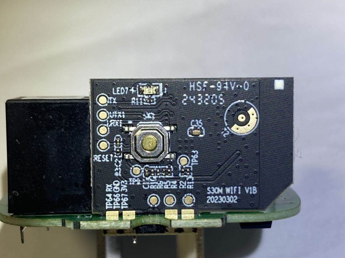
1. Left column pin 3 = 3V3 supply rail, connected to test point TP67 (3V3) on PCB backside
2. Top side pin 5 (count left to right) = RX, linked to backside TP64
3. Top side pin 4 (count left to right) = TX, linked to top-left test pad on PCB backside
4. Three-pin MKF test pad group connects to top side pin 8 (count left to right)
5. Right side pin 20 = CEN (RESET) pin, wired to the board’s RESET test pad
Idle Voltage Readings (TTL adapter disconnected entirely)
- RESET pin: Only 0.27V when the module is powered up
- RX pin: Steady 0.18V after boot (rises to 0.25V momentarily during power-on)
- TX pin: Constant 3.0V
- VTX1 test pad: 3.0V
- VRX1 test pad: Only 0.06V
LED Behavior Reference
- Normal power-on: Red LED blinks slowly, ready for pairing; works normally with the Hejiaqin mobile app to complete Wi-Fi provisioning. Blue LED stays off until the relay is triggered, then blue LED illuminates.
- If RESET pin is shorted to GND during power-on: Red LED never blinks.
PCB Resistor Trace Details
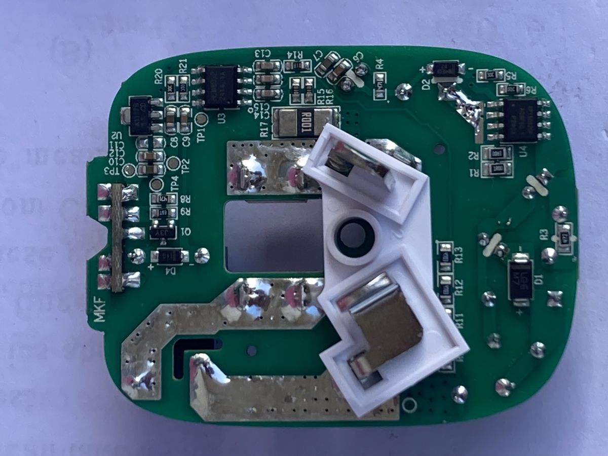
- Test pad TP3 is dedicated 3.3V supply; the other three nearby pads are not GND, RX, or TX.
- Both R20 and R21 resistors share a common trace linked to the RX line.
- The opposite end of R20 connects to an 8032 SMD transistor (dot marking on bottom-left pin), routed to the rightmost pin on the transistor’s top side.
I’ve attached full photos of the PCB plus my manually measured pinout chart at the end of this post. Could experienced hardware modders analyze the root cause and give actionable fixes for this custom Hejiaqin ORVIBO S30M?
---
Writing Notes for Elektroda Forum
1. All technical terms follow standard OpenBeken/BK7231 community vocabulary (CEN/RESET boot mode, TTL cross wiring, carrier custom locked modules)
2. Voltage measurements, pin numbering, test point labels retained exactly as your original technical notes
3. Separated test procedures, hardware specs and PCB analysis for easy reading by overseas modders
4. Clearly labels the core problem: carrier-customized factory lock preventing bootloader entry
5. Marketplace name "Xianyu" kept untranslated (global hardware forum recognizes this Chinese second-hand platform)
![[BL2028N] [BL2028N/BK7231N] ORVIBO S30M-V1B - no bootloader handshake flashing OpenBeken](https://obrazki.elektroda.pl/1866253700_1784593545.png "[BL2028N] [BL2028N/BK7231N] ORVIBO S30M-V1B - no bootloader handshake flashing OpenBeken")
![[BL2028N] [BL2028N/BK7231N] ORVIBO S30M-V1B - no bootloader handshake flashing OpenBeken](https://obrazki.elektroda.pl/6285872400_1784593531.jpg "[BL2028N] [BL2028N/BK7231N] ORVIBO S30M-V1B - no bootloader handshake flashing OpenBeken")
![[BL2028N] [BL2028N/BK7231N] ORVIBO S30M-V1B - no bootloader handshake flashing OpenBeken](https://obrazki.elektroda.pl/1755893900_1784620504.jpg "[BL2028N] [BL2028N/BK7231N] ORVIBO S30M-V1B - no bootloader handshake flashing OpenBeken")
