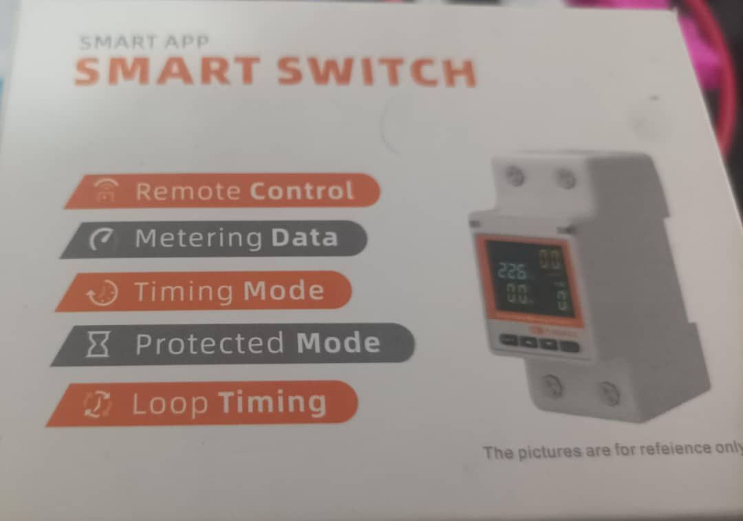


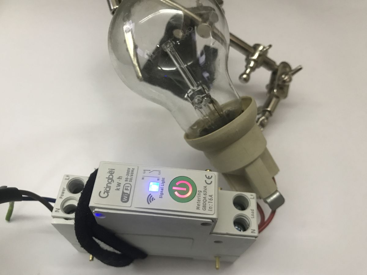
Today I’m taking a look at a device that arrived from Slovenia – a reader sent it to me, along with a few other gadgets. The GBDQA is a Wi-Fi-controlled, Tuya-compatible module offering programmable protection against over- or undervoltage, over- or under-current, or excessive power, as well as a built-in bistable relay. Here, I’ll show you its innards and modify it so that it works without the cloud, 100% locally, and can be connected to Home Assistant.
The reader has already drilled out the rivets; unfortunately, there are no screws here. It will be trickier to put it back together later, but it’s still no more difficult than programming LED lights, for example.
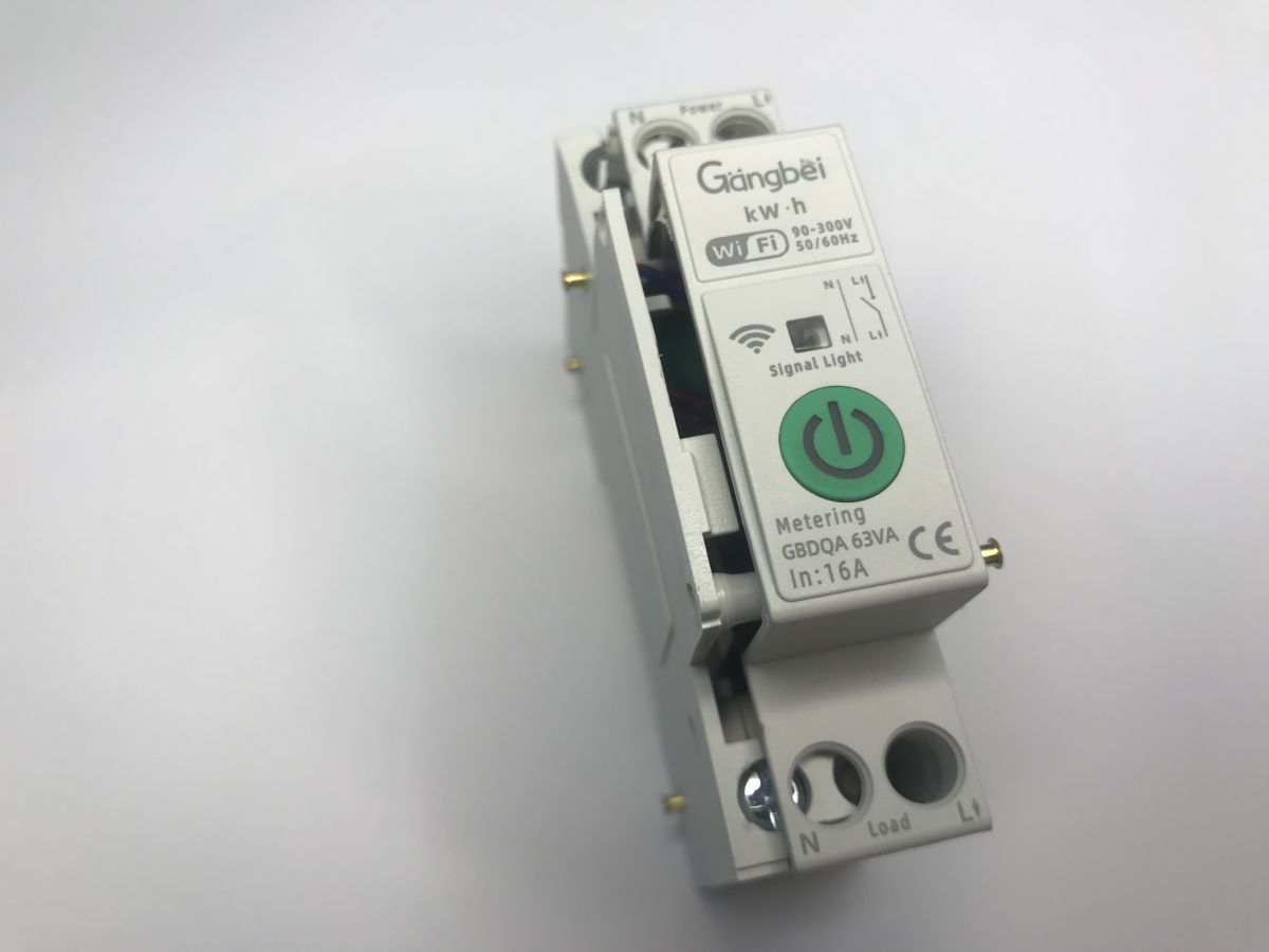
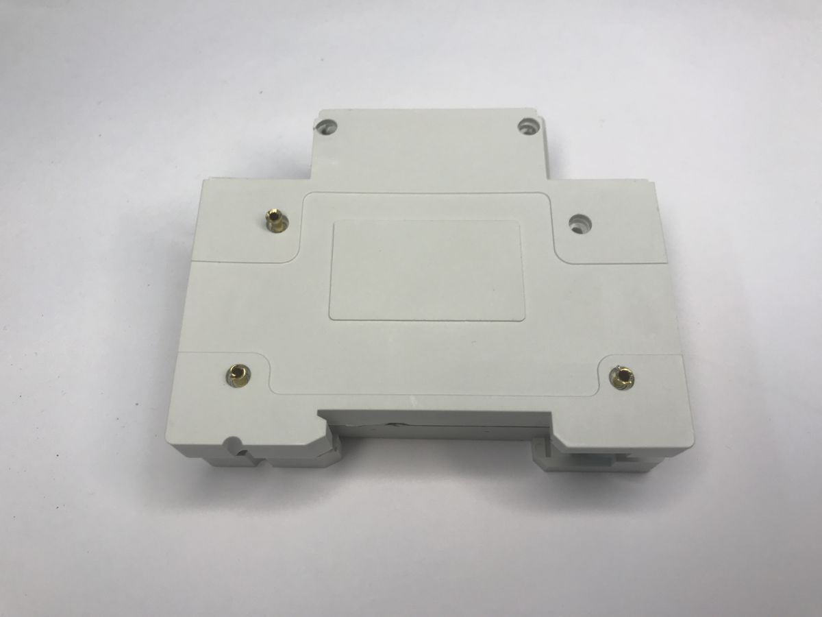
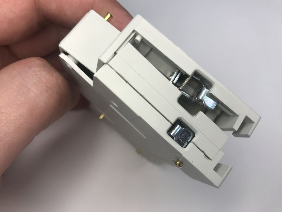
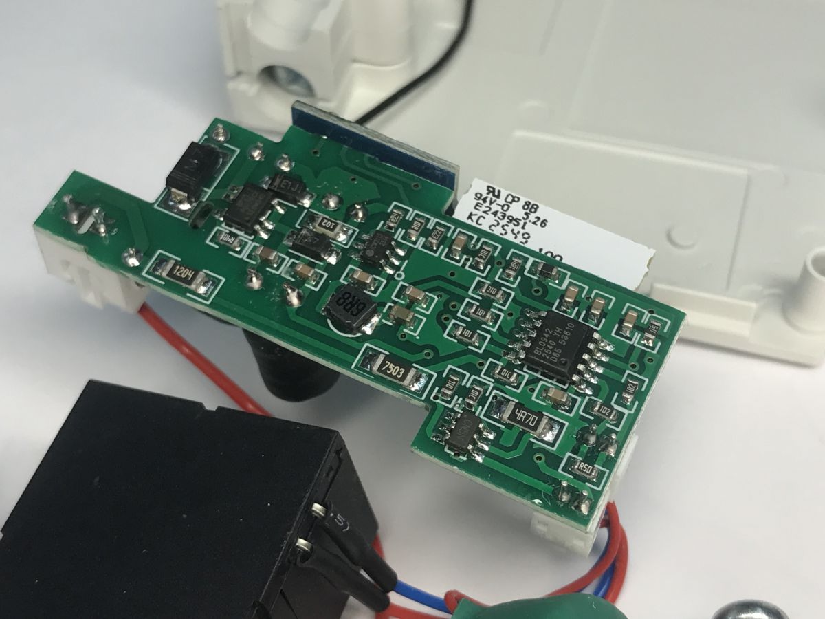
Let’s take a look inside. The circuit board is surprisingly small. How did they manage to fit the communication circuitry and the power supply in there? We’ll find out in a moment.
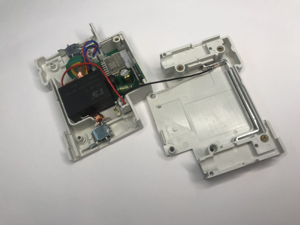
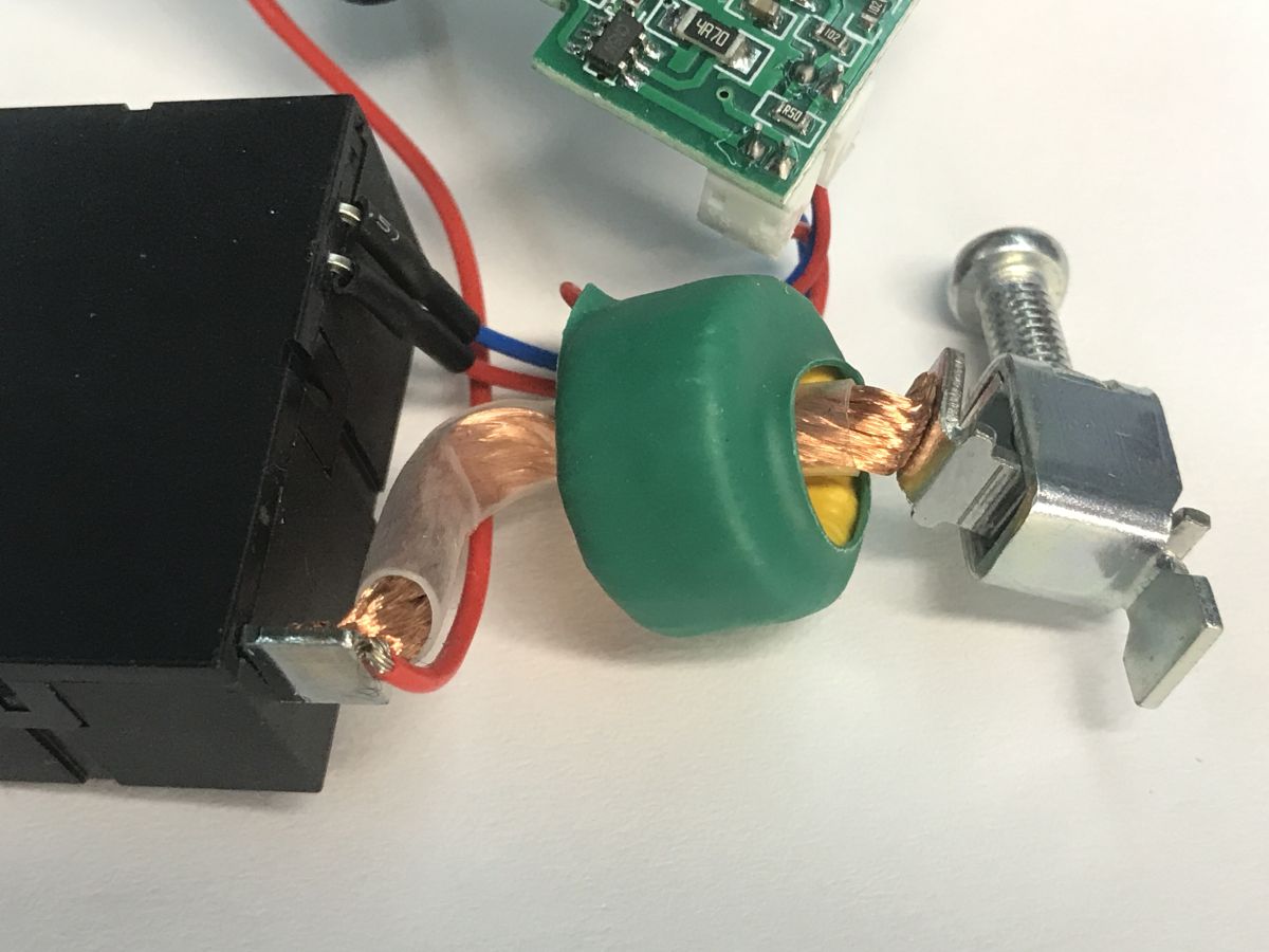
You can also see a bistable relay – it only requires power to switch states and, by its very nature, retains its state after power is lost – as well as a current transformer used to measure current.
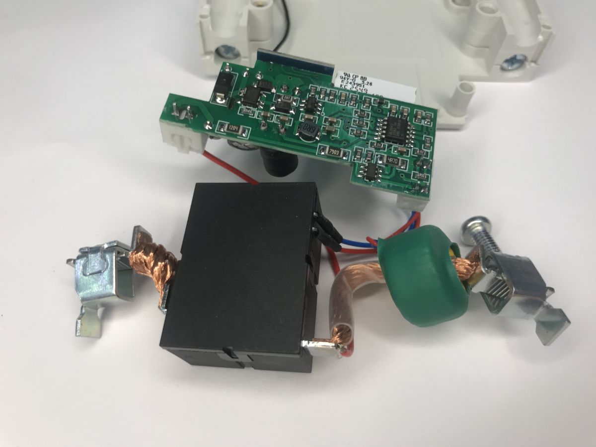
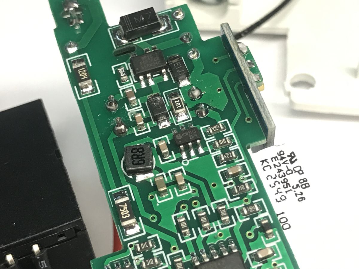
The other side of the PCB reveals further details – power is supplied by a BP2525 step-down converter; just behind it is a separate small converter to power the Wi-Fi module, whilst the BL0942 handles the measurement. It probably communicates with the main controller via UART, as usual.
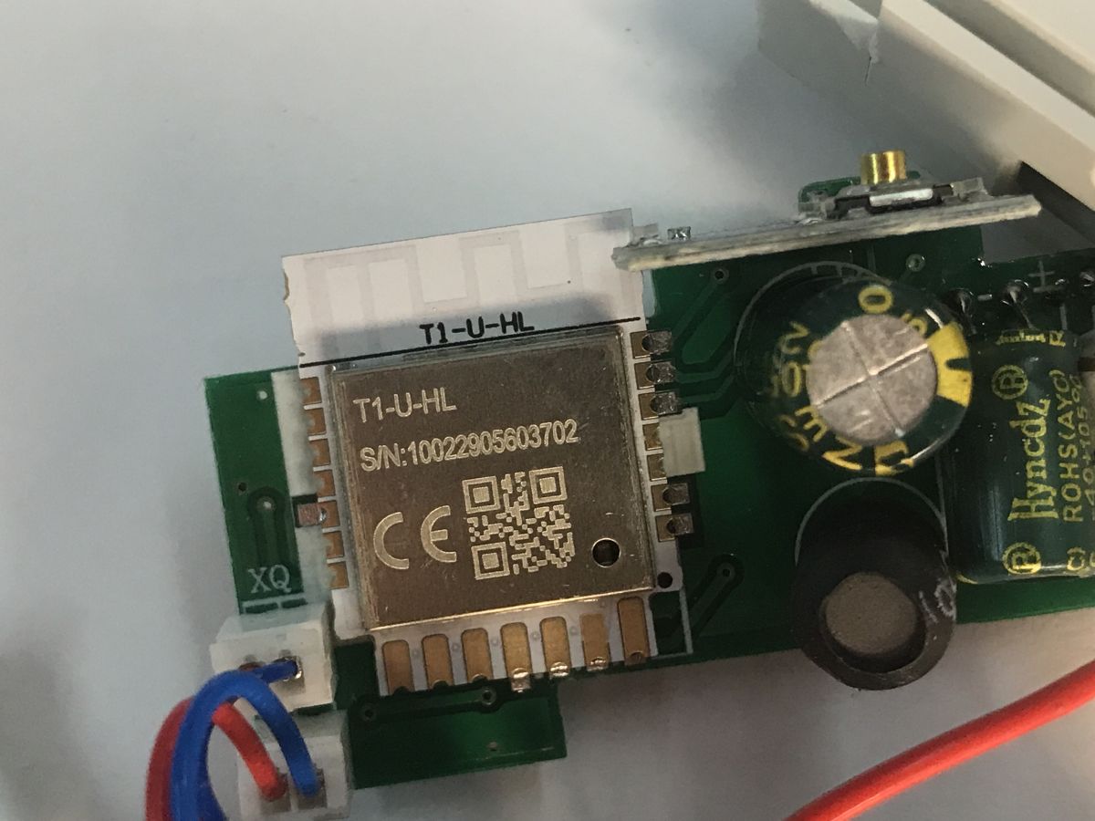
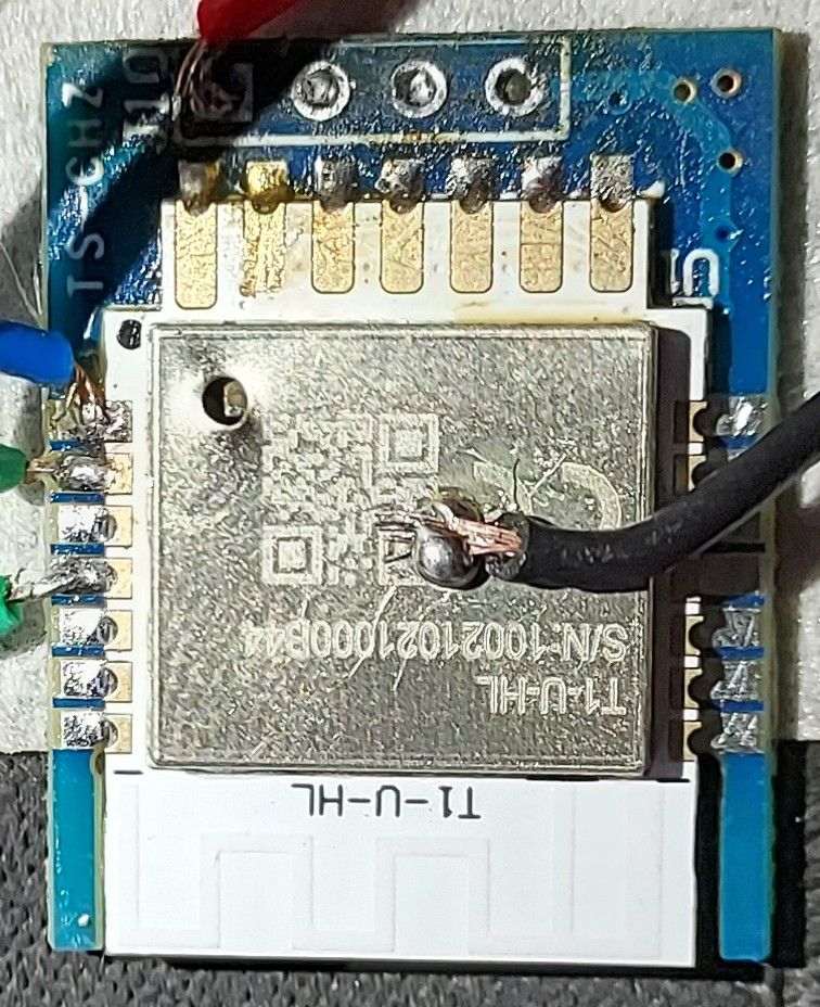
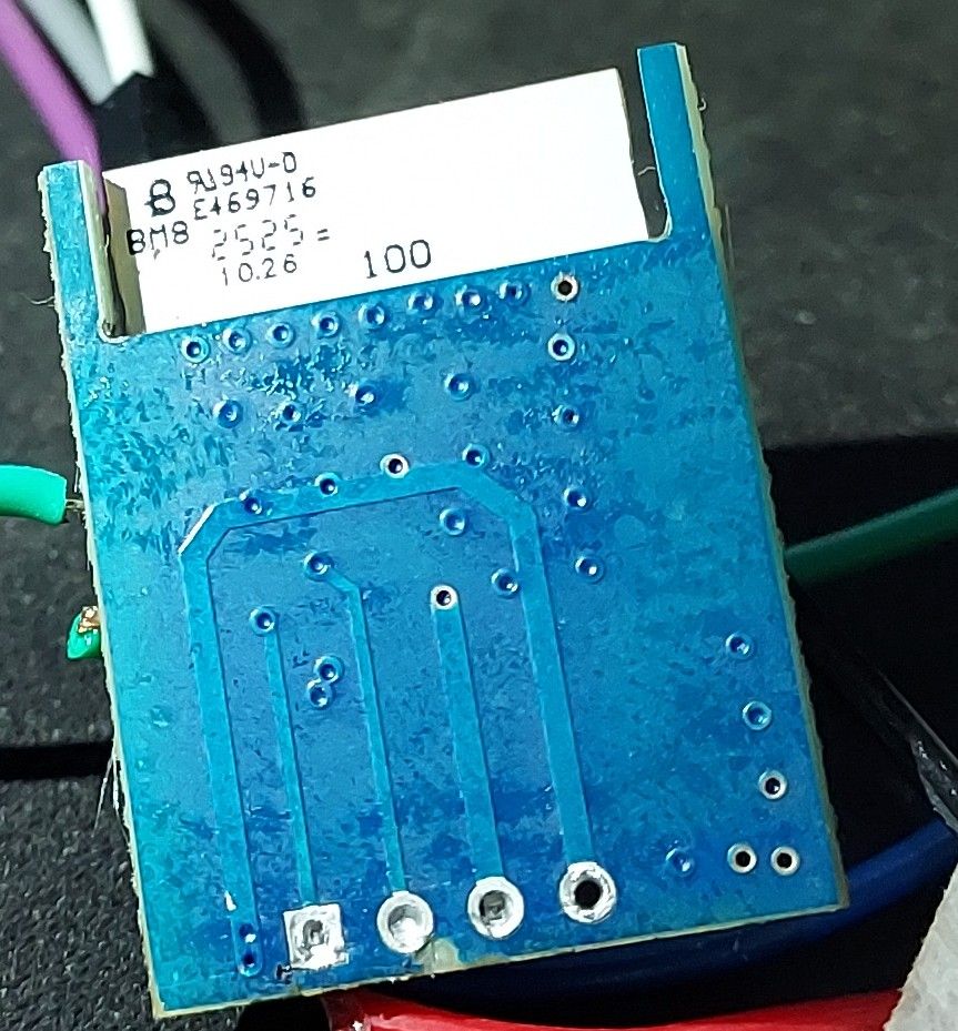
That leaves the Wi-Fi module – the T1-U-HL, which is a newer version of the CBU. It’s no longer the BK7231N, but the BK7238! However, this chip also supports OpenBeken , which is the recommended solution for freeing this type of device from the cloud.
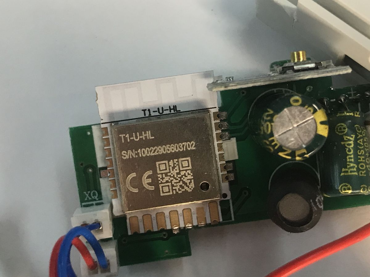
The pads are in the same places; you can flash the firmware.
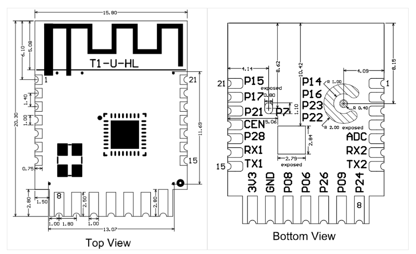
You’ll need a USB-to-UART converter and our flasher:
https://github.com/openshwprojects/BK7231GUIFlashTool
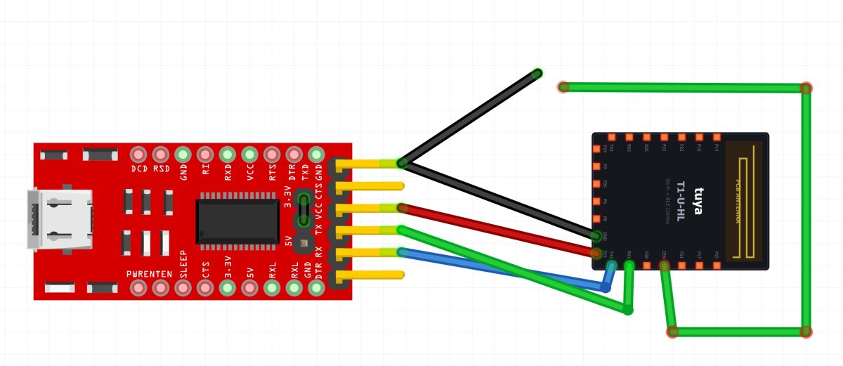
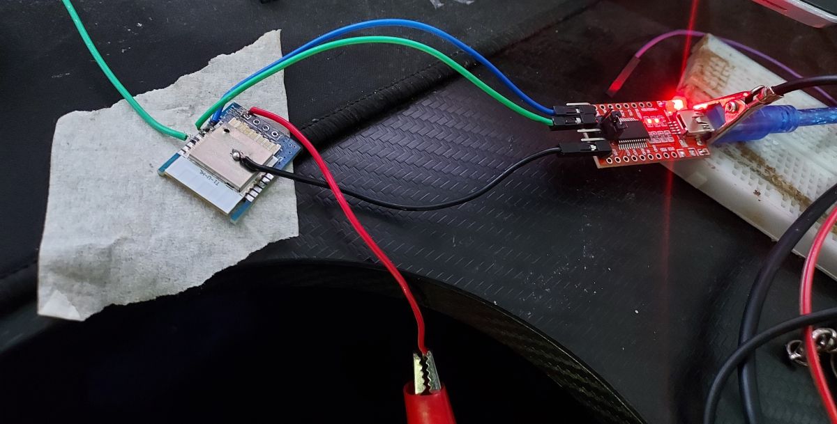
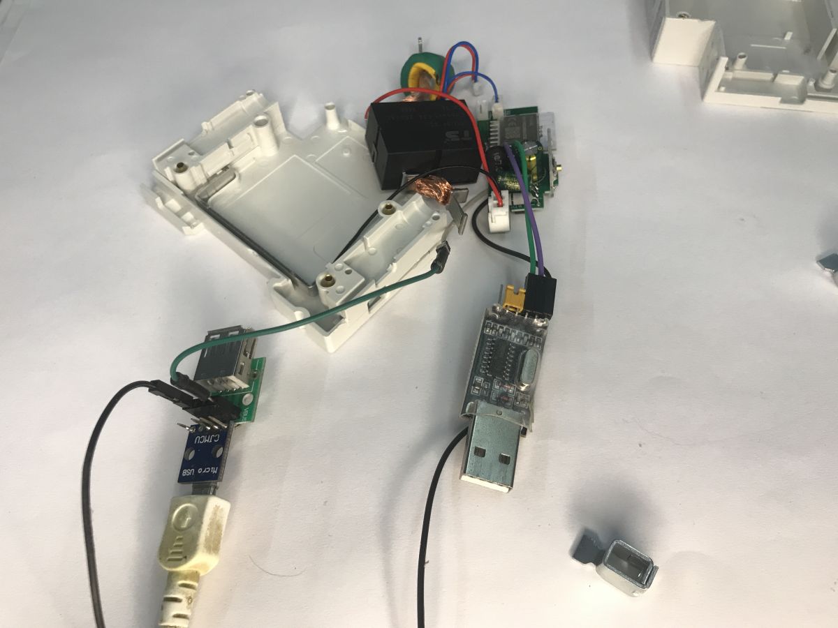
Solder the power supply and the RX and TX pads. Connect TX to RX, and RX to TX. The Wi-Fi module operates at 3.3 V; the USB supply is 5 V, but you can solder a capacitor in series before the second converter. Even based on its rated voltage (10 V), it’s clear that the first converter likely outputs 5 V and the second 3.3 V.
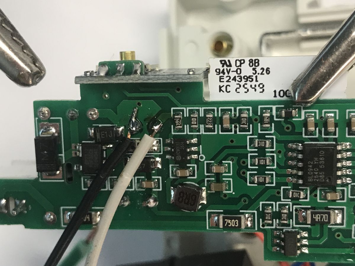
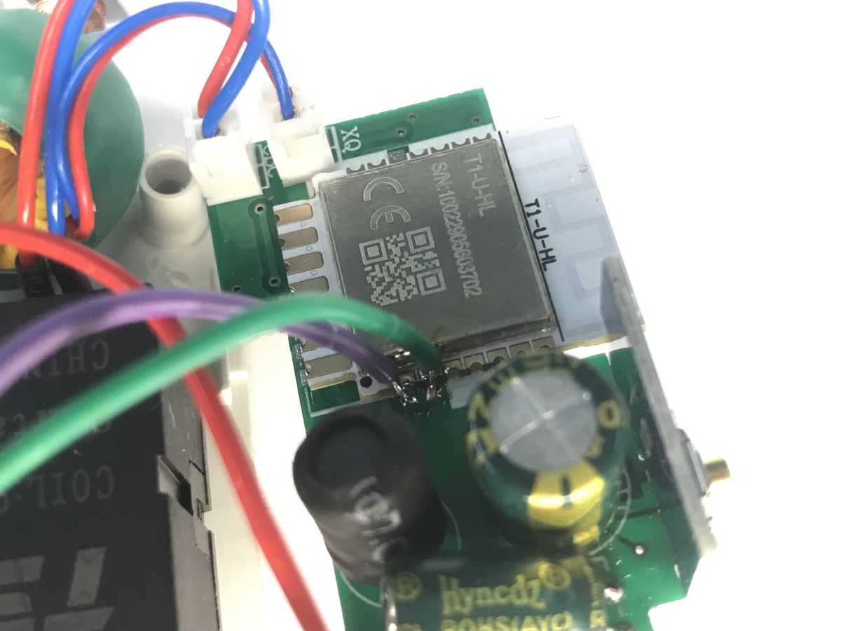
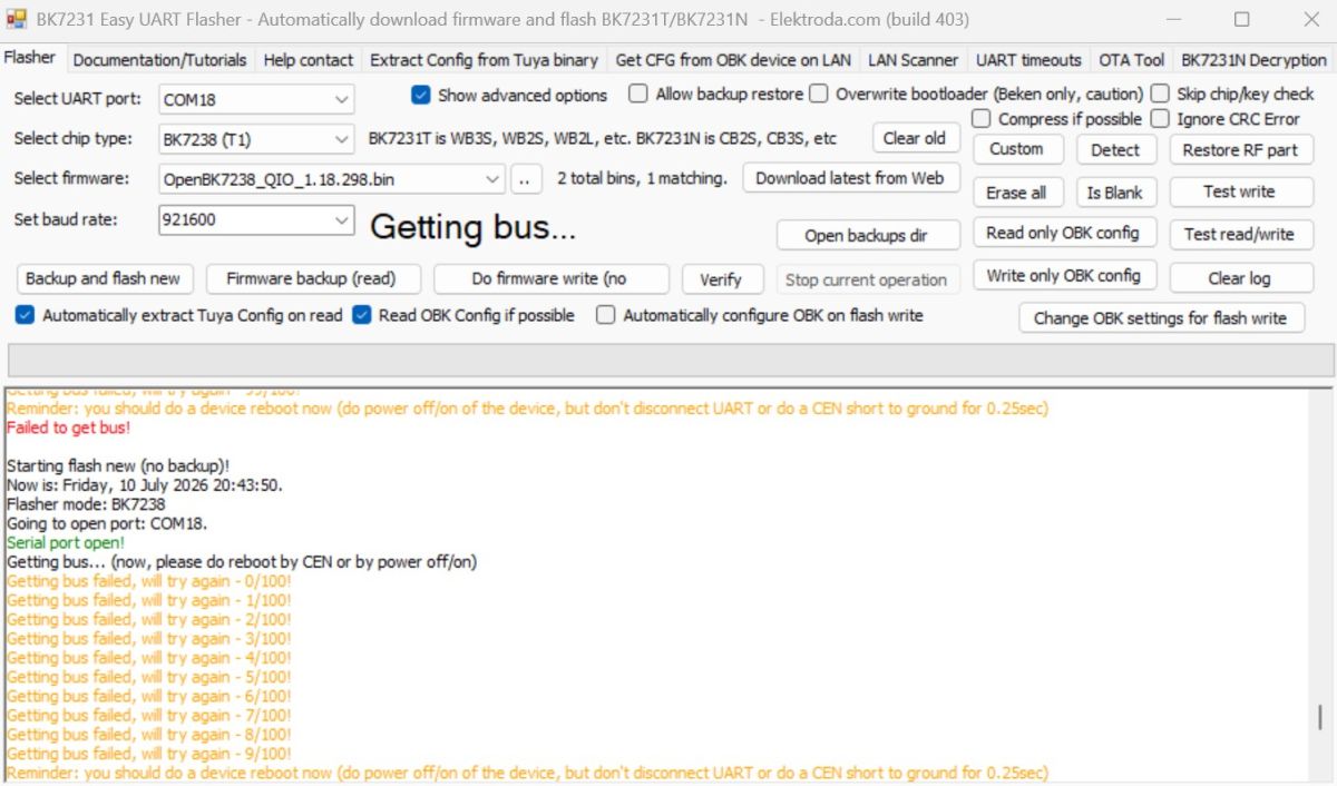
Of course, we carry out all this with the device disconnected from the mains. The flasher will now require the device to be restarted to begin the flashing process. However, there is a problem here, as there is a capacitor on the board, so restoring the power supply causes the current surge drawn through it to overload the USB port. For this reason, I used a second cable for the power supply:
First, you need to make a flash copy. This will allow you to discover the GPIO configuration.
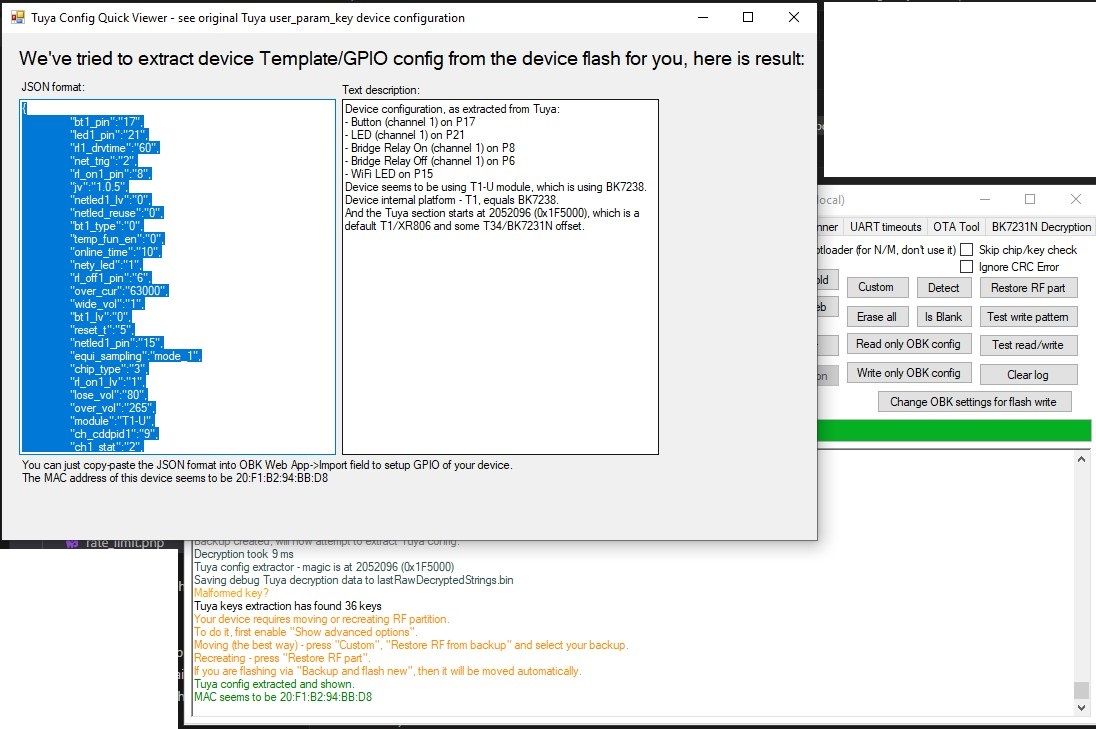
Tuya JSON:
Code: JSON
Verbal interpretation:
Device seems to be using T1-U module.
- WiFi LED on P15
- LED (channel 1) on P21
- Button (channel 1) on P17
- Bridge Relay On on P8
- Bridge Relay Off on P6
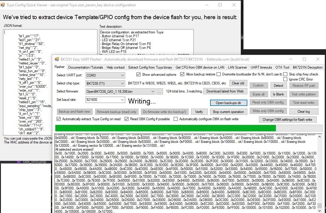
This will help us with the configuration. You can now flash the OBK:
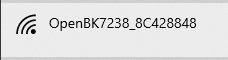
Once uploaded, an open AP will be created – you can configure your network settings via the IP address 192.168.4.1:
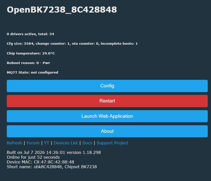
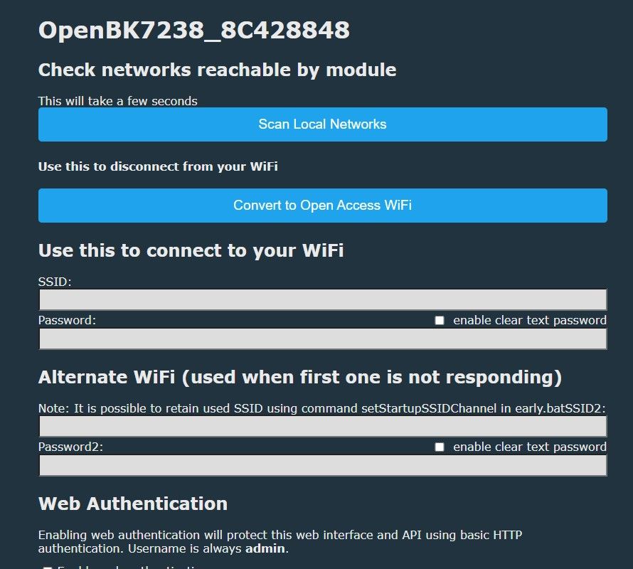
The device will join your Wi-Fi network:
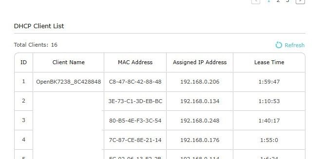
Then, in the Web App You can import the JSON file downloaded by Flasher:
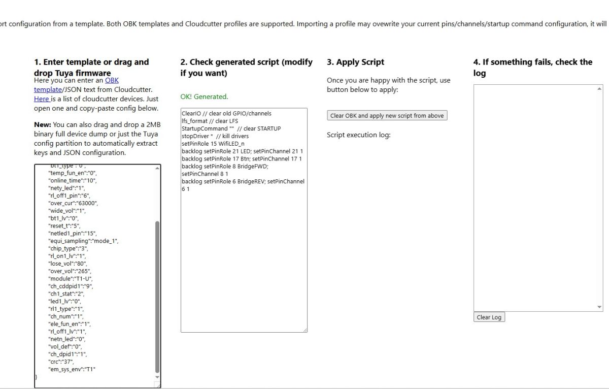
This should allow us to control the relay:
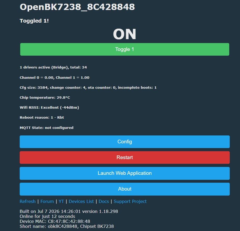
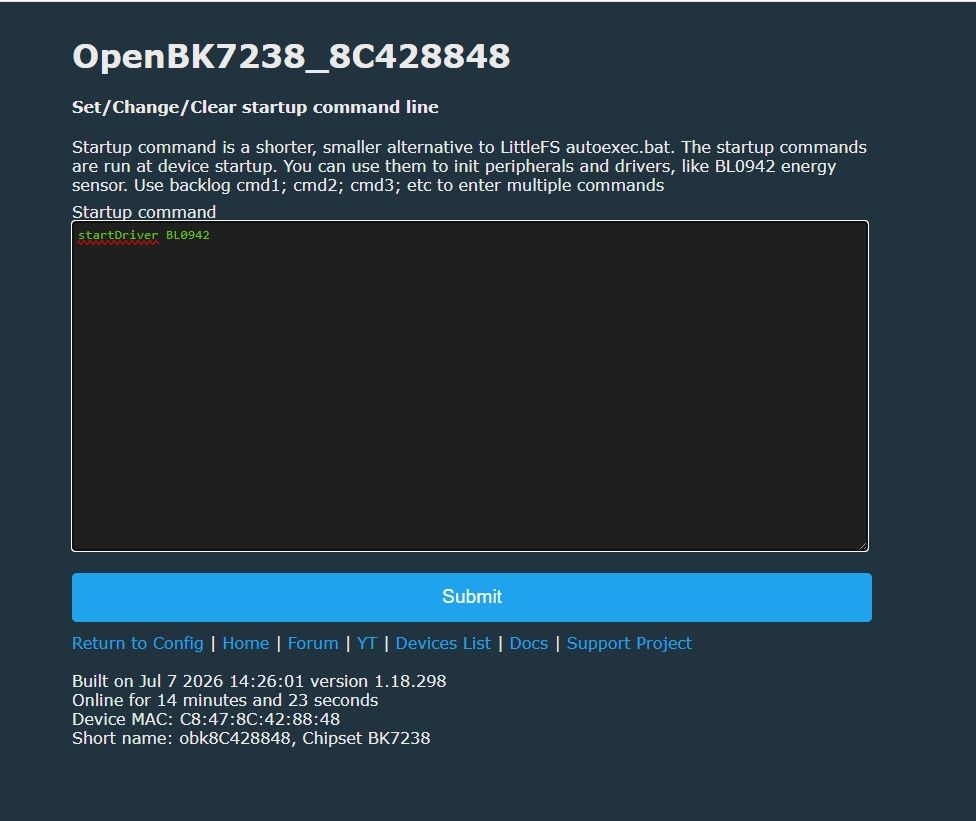
All that remains is to enable the measurement system – enter the command in ‘short startup command’ and reboot:
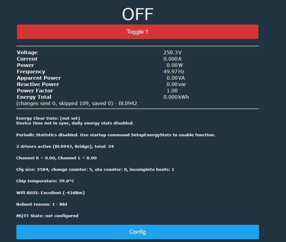
We now have measurements, but they are not perfect:
Calibration is required – just as in Tasmota. A second meter is needed; connect it before the one being calibrated, then apply a sample resistive load, e.g. a light bulb, and enter the readings from it into the Web App:
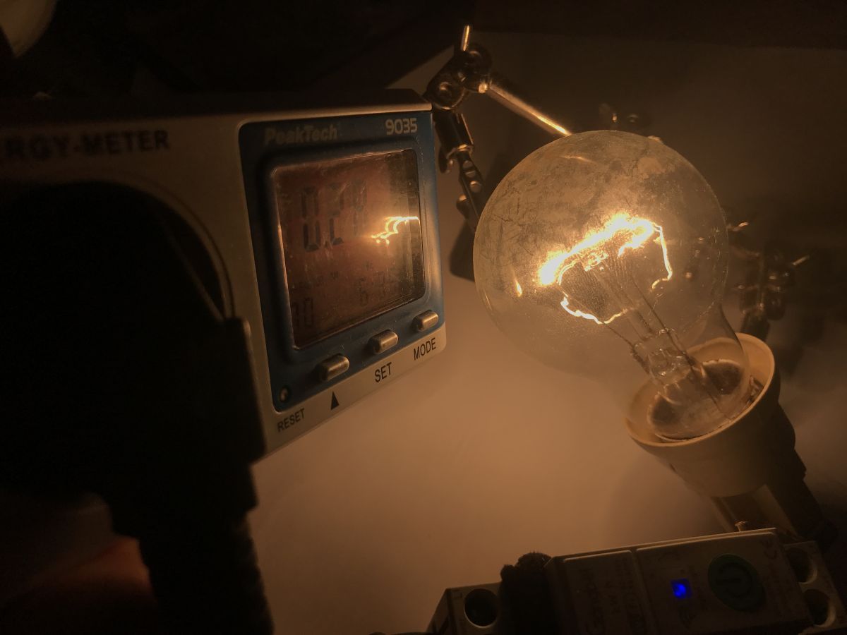
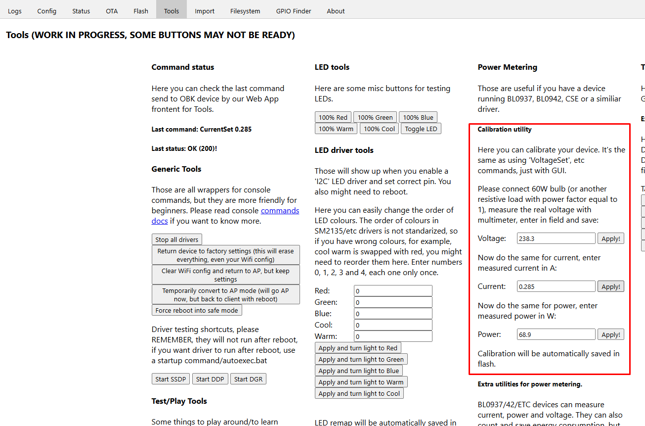
You might also consider subtracting the power consumption of the gadget itself here, but these are negligible values. From this point onwards, the values displayed on the panel will be similar to those shown by the meter used as a reference.
You can now pair the device with Home Assistant, but we’ve already shown how to do this on our channel:
To sum up, the device is tiny and compact, yet it can carry out automations. Normally via the Tuya cloud – but following my intervention, it now operates entirely locally. Thank you for providing me with this equipment for testing; I’ll be testing the remaining devices from the package, after which the whole lot will be returned to the reader. Do you use modules of this type? Please feel free to comment.
PS: A copy of the original post: https://github.com/openshwprojects/FlashDumps/commit/5d9b9c30284a0d2120ee75f4412199667a231b04
Cool? Ranking DIY Helpful post? Buy me a coffee.