







Here, I will present the versatile ESP32-S3-POE-ETH-8DI-8RO module, which offers a wide range of communication and control capabilities. The device combines Ethernet, Wi-Fi, Bluetooth, digital inputs and relay outputs, making it suitable for various projects in the fields of automation and IoT. Furthermore, PoE support simplifies installation and power supply in hard-to-reach locations. The whole thing is easy to programme using Visual Code and PlatformIO, which I will also demonstrate here – my examples will cover the device’s basic functionality.
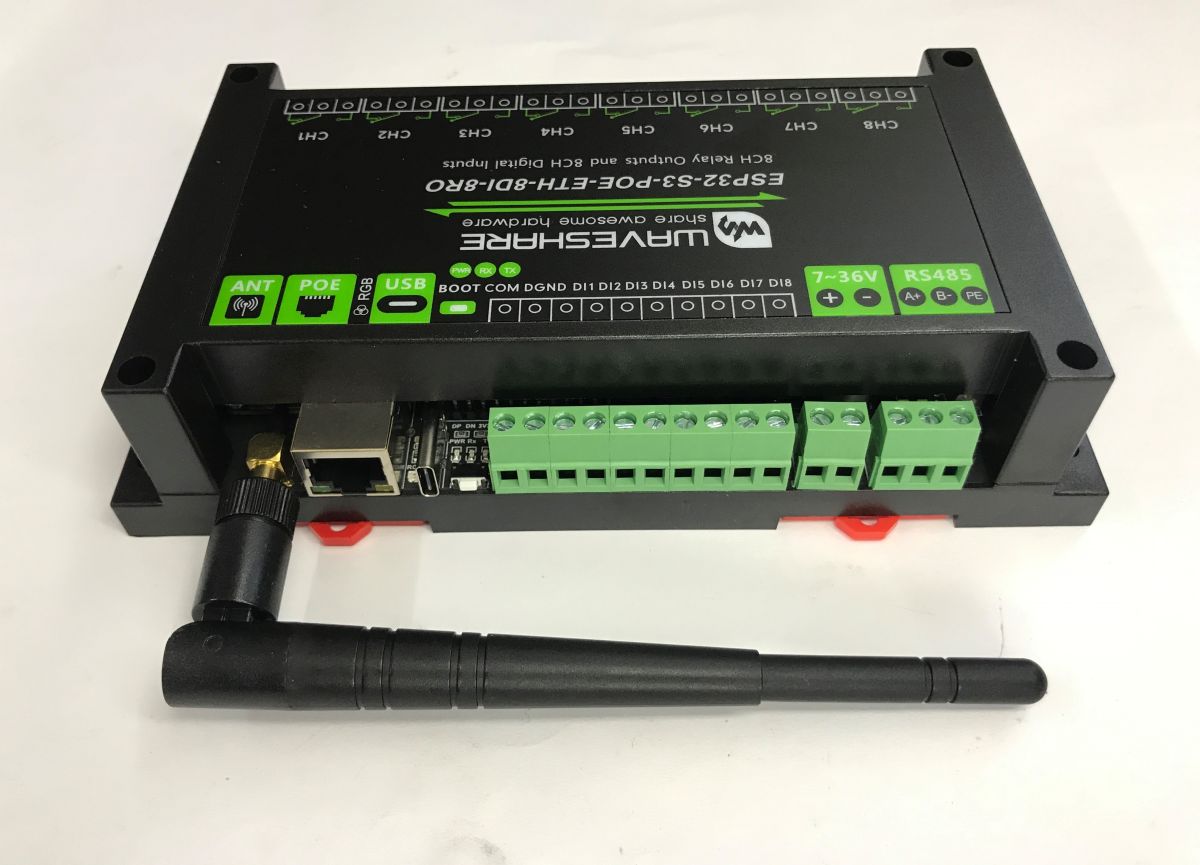
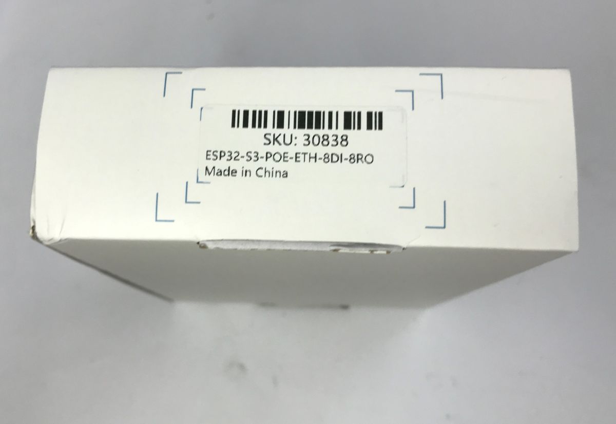
Modules of this type are often marketed as ‘industrial’. The model presented here has the SKU code 30838.
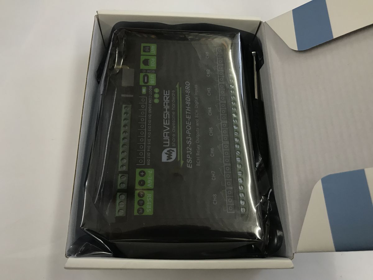
The pack includes the module, an antenna and a small screwdriver.
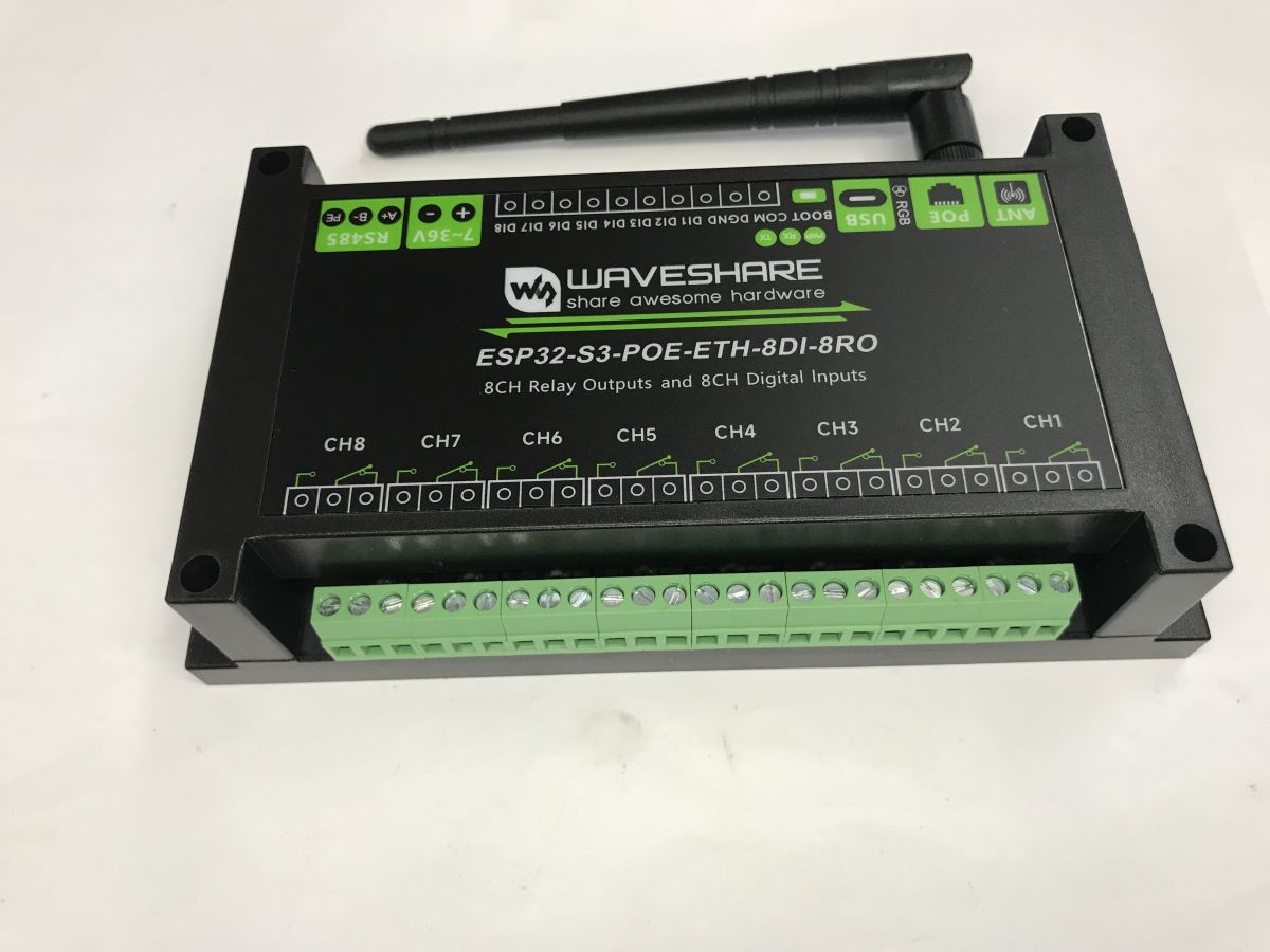
On the front, there are 8 relay outputs – both normally open and normally closed, as well as a common contact, of course.
On the rear are an Ethernet (PoE) port, an antenna, an RGB LED (WS2812), a boot button, digital inputs, a power supply (up to 36 V) and an RS485 port.
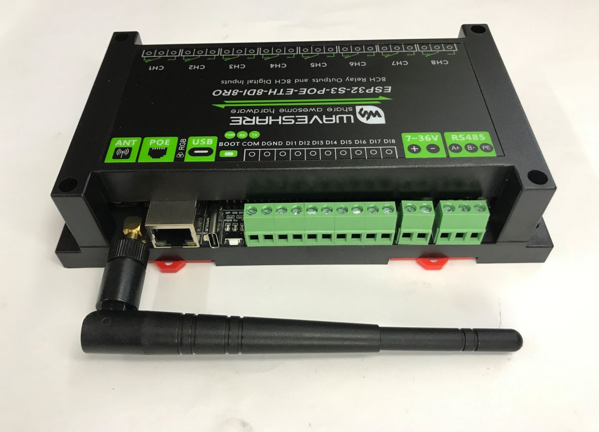
However, I can’t see the RESET button on the ESP here; it’s only visible once the cover has been removed.
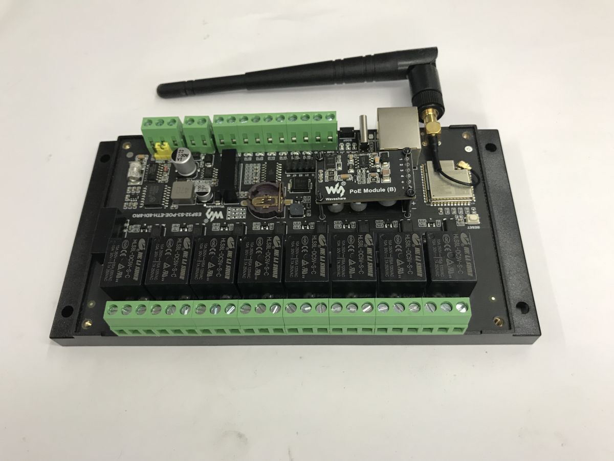
Now we can refer to the documentation from WaveShare. What do we have on board:
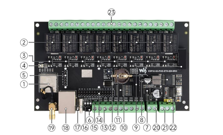
1. ESP32-S3
Operating frequency up to 240 MHz, with 2.4 GHz Wi-Fi and BLE
2. High-quality relay
Contact rating per channel: ≤10A 250V AC or ≤10A 30V DC
3. Optocoupler isolation
Prevents interference with the control system from an external high-voltage circuit connected to the relay
4. RESET button
5. PoE port
Option to connect a PoE module (PoE port version only)
6. BOOT button
7. Power supply circuit
8. Digital isolation
Prevents interference with the control circuit from external signals
9. Power supply isolation
Ensures a stable isolation voltage; no additional power supply is required for the isolated side
10. Bidirectional opto-isolator isolation
11. RTC battery connector
12. Buzzer
13. Digital input interface
14. Pin connector
Ability to connect other devices
15. Operating status indicator
PWR: power indicator
RXD: RS485 receive indicator
TXD: RS485 transmit indicator
16. USB interface Type-C
For powering the module, firmware updates and USB communication
17. WS2812 RGB colour LED
Controlled via GPIO38 pin
18. Network port
19. External antenna socket
Female SMA connector, for WiFi and Bluetooth wireless communication
20. Screw-type power connector
Supports a wide voltage range of 7–36 V DC
21. RS485 communication interface
Supports connection of external RS485 devices
22. RS485 terminating resistor
Built-in 120Ω resistor, enabled via a jumper
23. Screw-type relay terminal
Makes it easier to connect devices
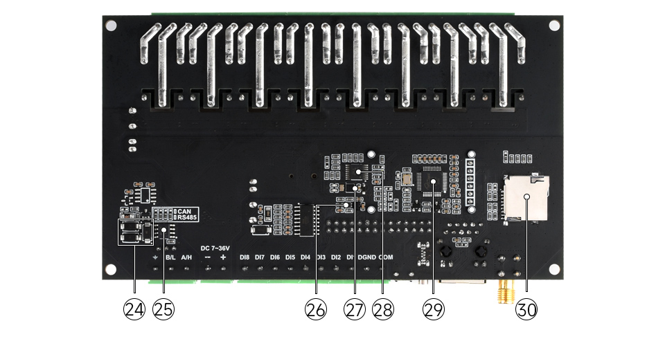
24. Built-in TVS (surge suppressor) Effectively suppresses surge voltages and short-term voltage spikes in the circuit
25. RS485 conversion circuit
26. MP1605GTF-Z DC-DC power supply module
27. PCF85063ATL RTC circuit for timing tasks
28. TCA9554PWR Extends I/O lines for relay control
29. W5500 Extends 10/100Mbps network connectivity via the SPI interface
30. TF card slot Supports external TF cards for storing images and files
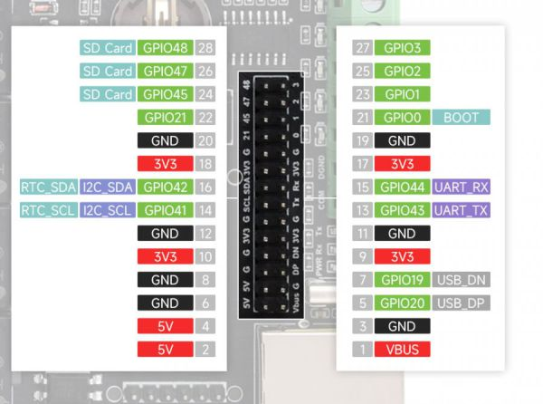
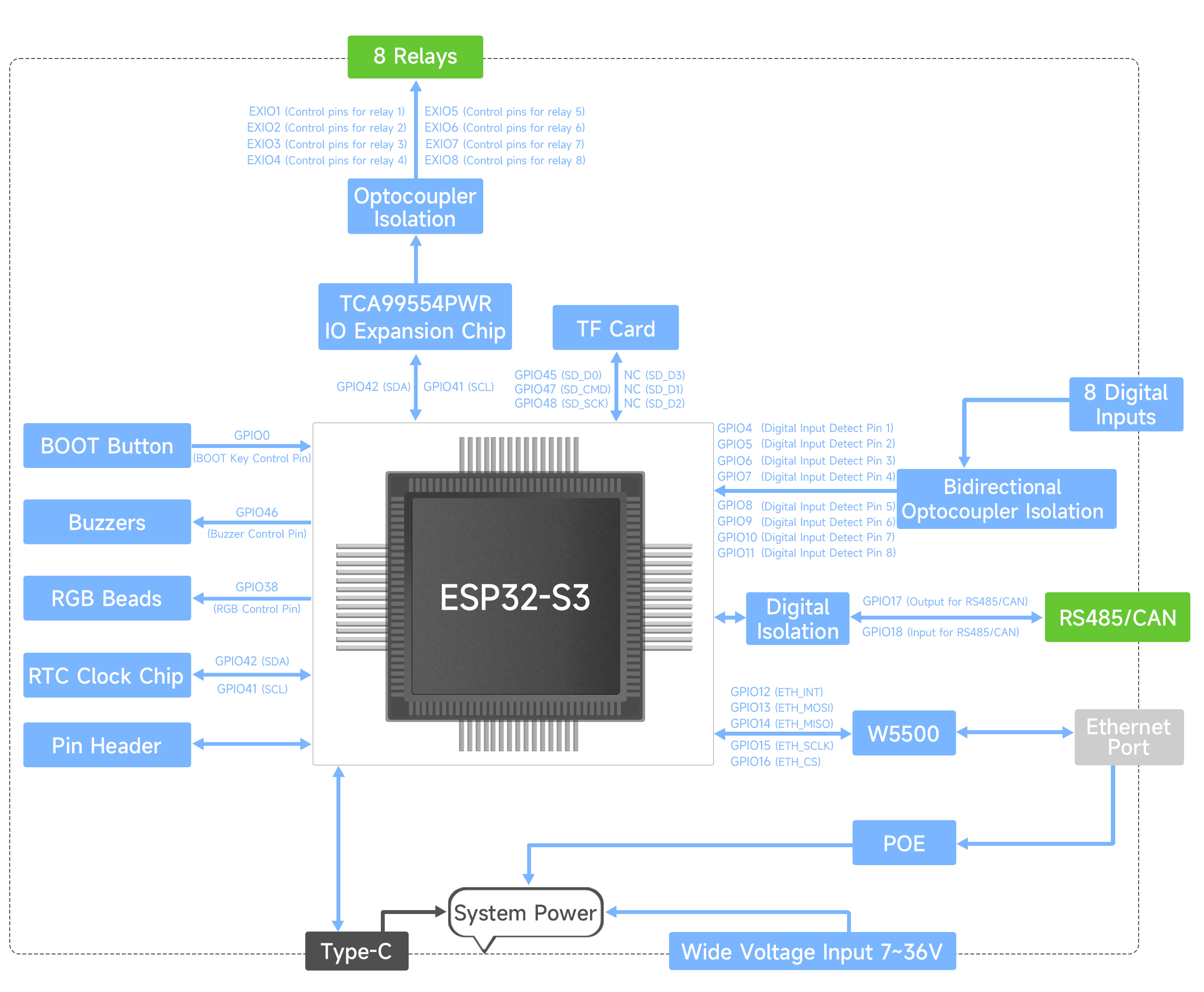
Schematic diagram:
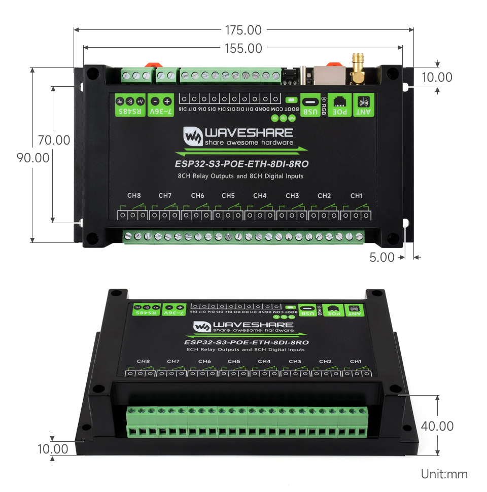
Dimensions:
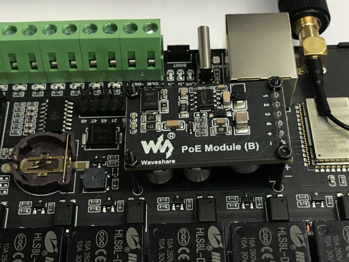
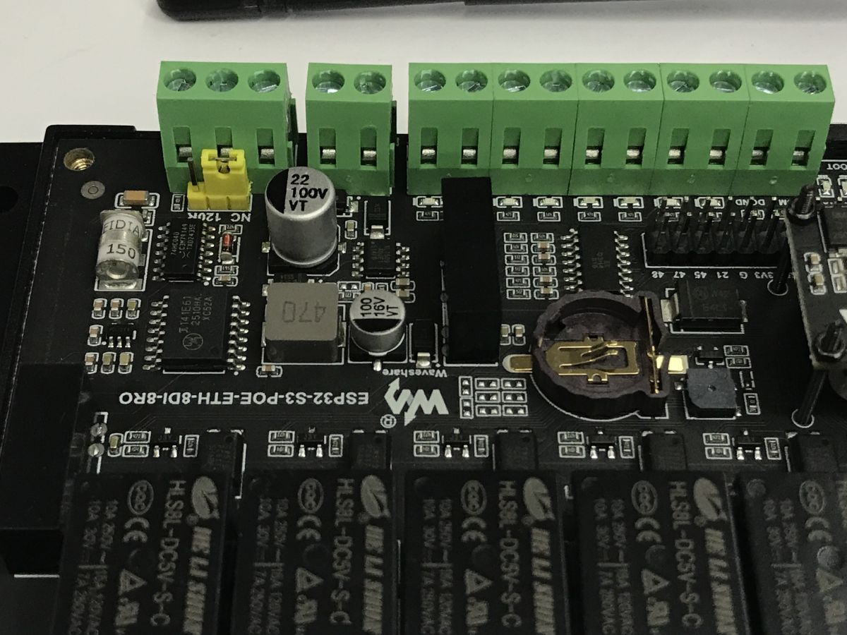
Additional photos:
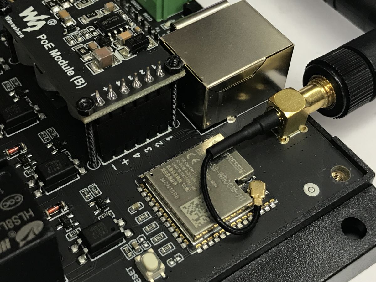
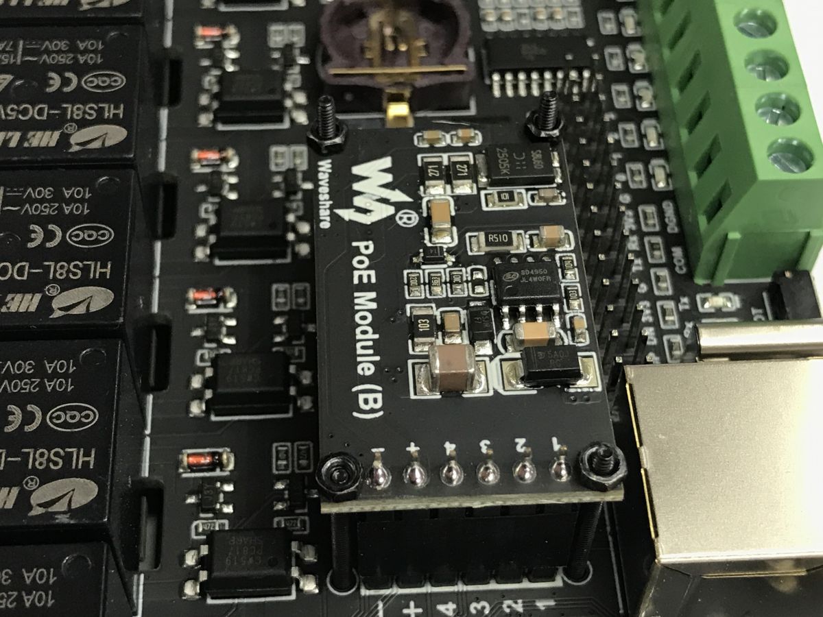
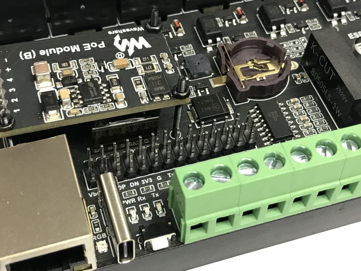
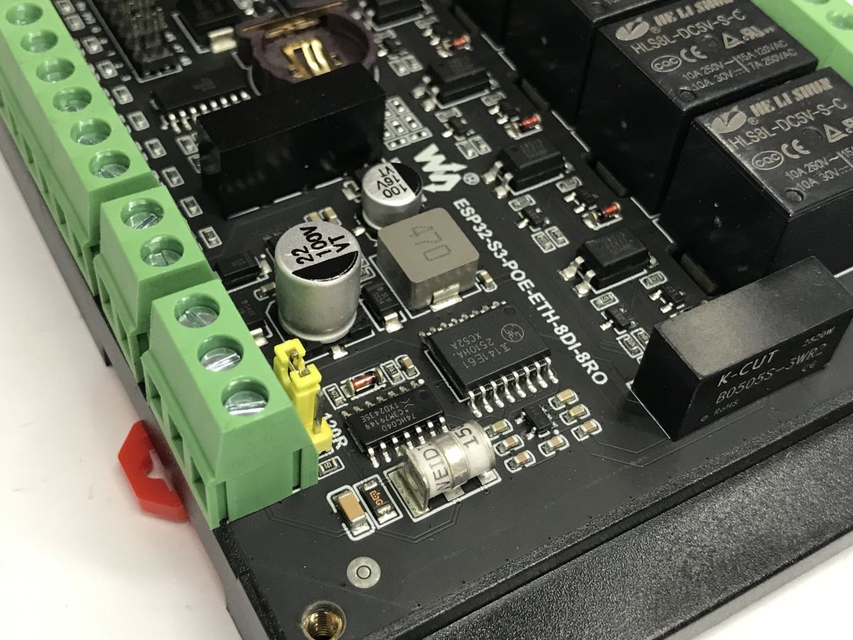
Hello World LAN
The programme is uploaded via USB. To make working with the UART easier, I have redirected the log output to the CDC, i.e. the virtual serial port.
The platformio.ini file:
[env:esp32-s3-poe-eth-8di-8ro]
platform = https://github.com/tasmota/platform-espressif32/releases/download/2024.08.10/platform-espressif32.zip
board = esp32-s3-devkitc-1
framework = arduino
monitor_speed = 115200
upload_port = COM60
monitor_port = COM60
build_flags =
    -D ARDUINO_USB_MODE=1
    -D ARDUINO_USB_CDC_ON_BOOT=1
The LAN controller is connected via SPI. It requires the pins to be mapped correctly.
Code: C / C++
When the programme starts, we initialise the SPI and Ethernet. The rest will run in the background.
Code: C / C++
The library responsible for the connection automatically publishes events that can be used to monitor the connection status. The router’s DHCP automatically assigns an IP address to the board.
Code: C / C++
All that remains are the servers – we simply define the resources available there and the content they return, along with the MIME type. All HTTP handling is carried out by the WebServer library.
Code: C / C++
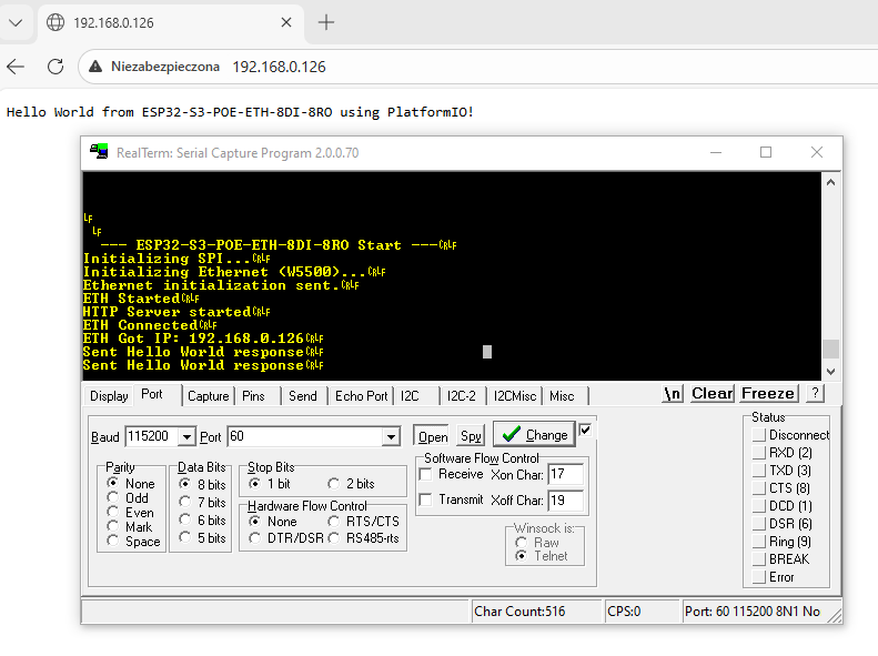
The result – the server is accessible via the cable and is working correctly.
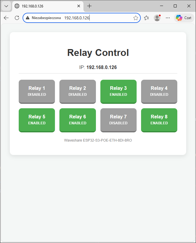
Relay control
There are eight relays, but they are not accessible via standard GPIO pins. The TCA9554 pin expander, controlled via the I2C interface, is used to control them. This allows the number of GPIOs required to be reduced to just two (SCL and SDA) and enables the bus to be shared with other devices.
We include the I2C header, define its pins, the TCA9554 address and the addresses of its registers:
Code: C / C++
Next, we need a function that sends a value to a specific TCA9554 register:
Code: C / C++
I store the relay states as a byte – the individual relays correspond to its respective bits. When a change occurs, I send this byte to the expander.
Code: C / C++
Improved HTML page
Code: C / C++
Handling a request to toggle a specific relay:
Code: C / C++
We still need to set the expander’s pin mode once at start-up:
Code: C / C++
This is how the relays can be controlled. This isn’t an ideal solution and isn’t really suitable for the final version of the product, as, for example, sending a command twice (e.g. due to a network issue) will toggle the relay’s state twice, but it’s perfectly fine for a small demo.
WS2812 control
The WS2812 is an individually addressable coloured LED, which is used here to indicate the device’s status. Normally, multiple WS2812s are used to create strips and various LED gadgets where animations are played, but here we have just one. However, this does not prevent us from using the same library as for strips – for example, Adafruit NeoPixel.
We add it to PlatformIO:
lib_deps =
    adafruit/Adafruit NeoPixel @ ^1.12.0
We define the number of LEDs and the pin used for communication, then create an object representing the LED strip (pixels) in the appropriate mode:
Code: C / C++
All that remains is to add the frontend – a ready-made colour selection form using HTML:
Code: C / C++
And finally, the connection – receiving the packet that sets the colour:
Code: C / C++
Panel:
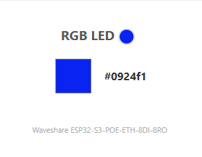
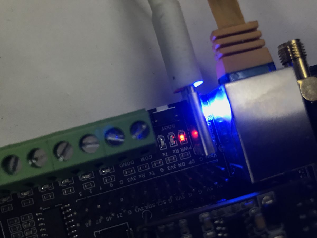
Result:
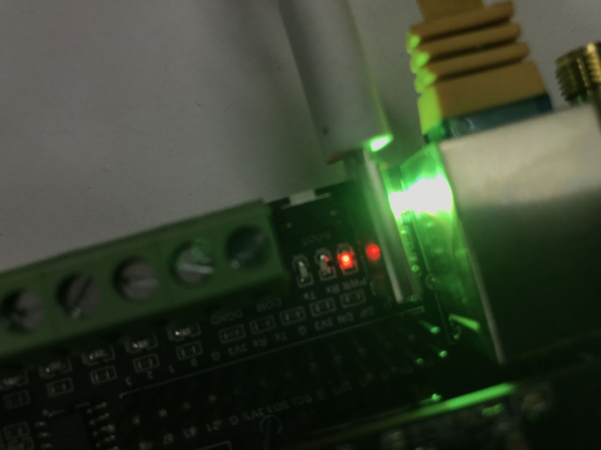
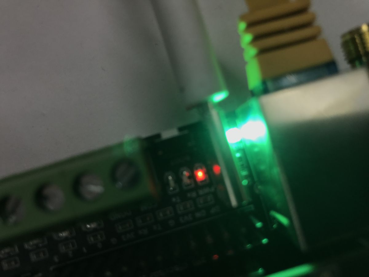
Buzzer control
Finally, something simple but equally important. A visual signal from the WS2812 is one thing, but an audible signal is also useful. That’s why we have a buzzer on board. Let’s define its pin and the associated constants. The buzzer operates using PWM, as this allows us to generate an audio signal with adjustable frequency and volume using a digital pin on the microcontroller. By sending rapid pulses at a specific frequency and duty cycle, the buzzer vibrates continuously, creating the impression of a tone that we can control via software.”
Code: C / C++
We use ledc to control PWM. ledc in the ESP32 is a built-in hardware module for generating a PWM signal on selected pins
Code: C / C++
The function that plays the “beep” is blocking; it simply sets the duty cycle, waits a moment, and then clears it. I decided I could get away with it in this demo.
Code: C / C++
I’ve also added a button for this on the HTML panel.
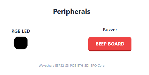
The result (please watch with sound):
Inputs
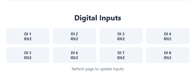
That leaves the digital inputs. Interestingly, these are directly on the ESP32 pins – there’s no expander here. GPIO pins 4, 5, 6, 7, 8, 9, 10 and 11 are used. I’ve put them in an array so they can be scanned on the fly whilst generating the web panel:
Code: C / C++
They need to be initialised beforehand, just as is traditionally done with Arduino pins:
Code: C / C++
And this is what the scan looks like – a simple
digitalRead:
Code: C / C++
Result:
What’s heating up on the board?
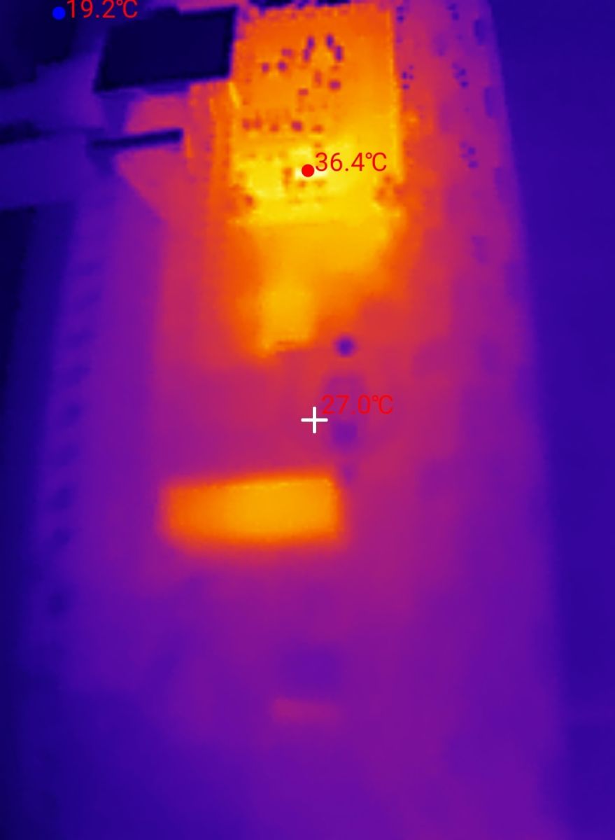
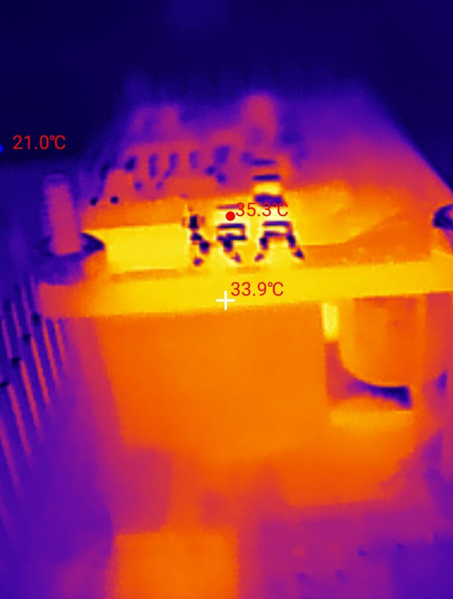
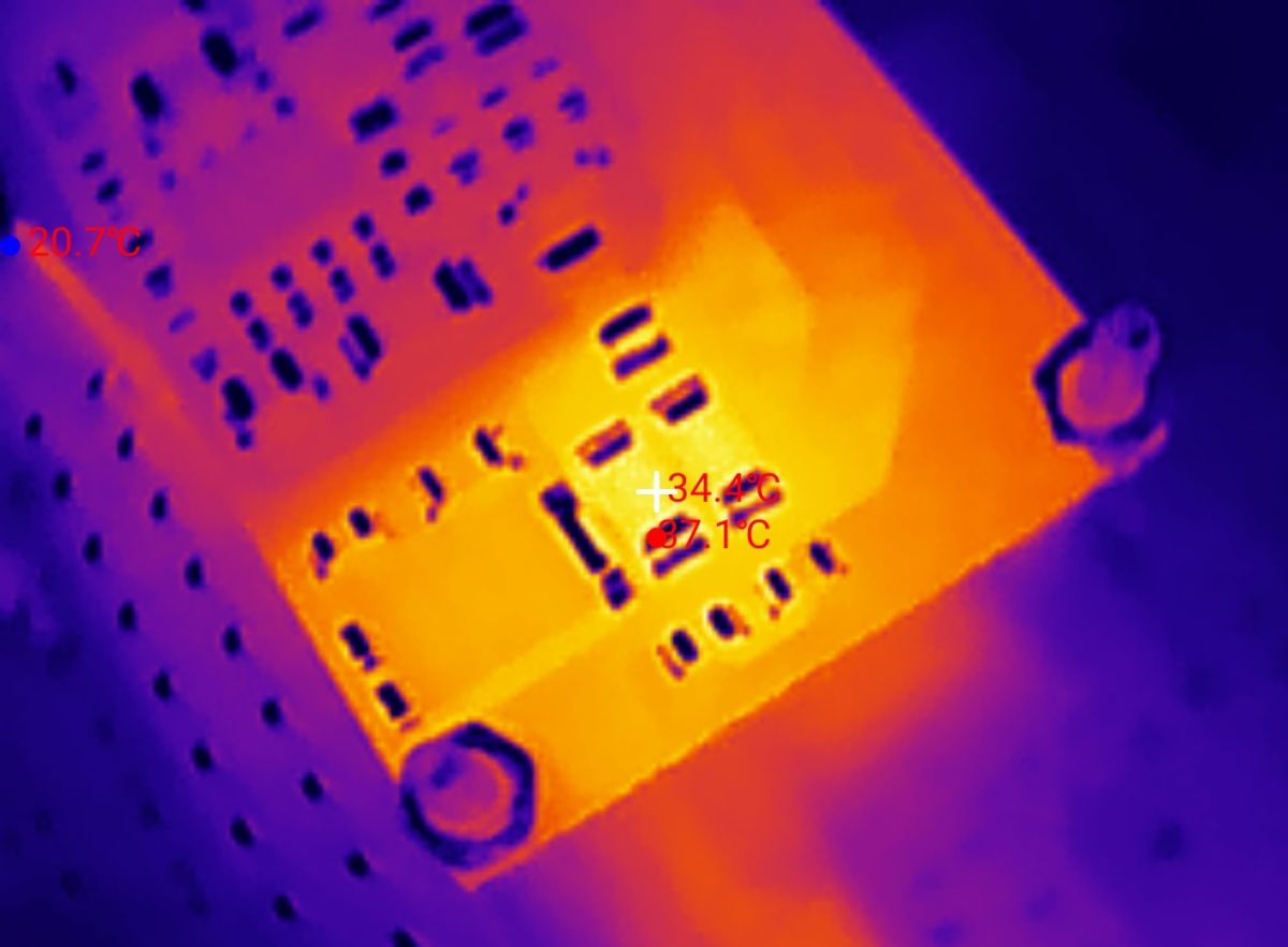
Finally, just a quick test, out of curiosity. What gets the hottest? It looks like the PoE board… or, more precisely, the resistor. That’s strange to me, as I’m powering the board from a USB port.
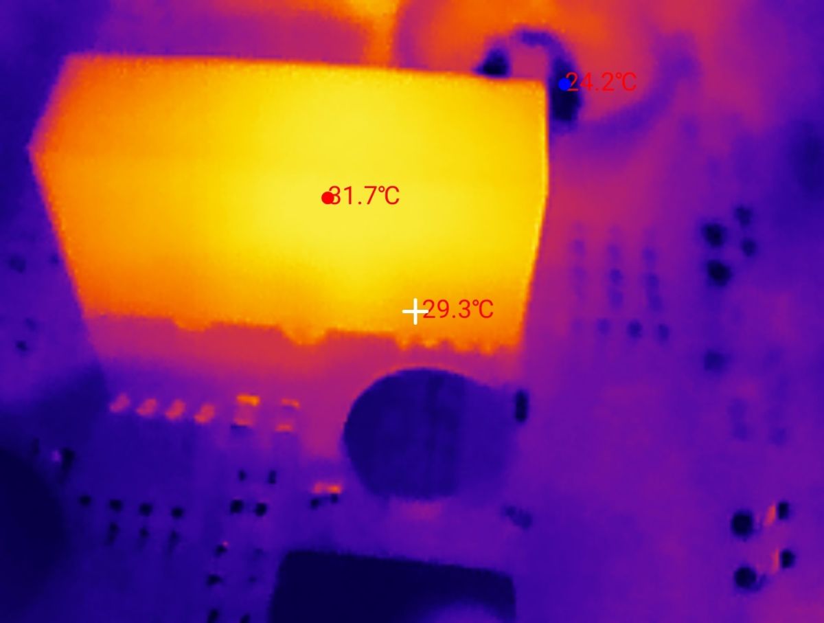
The power supply circuit on the output side is also getting hot:
Summary
To sum up, this was a brief overview of the ESP32-S3-POE-ETH-8DI-8RO. We managed to get the basic functions up and running – communication via Ethernet, outputs (relays, LEDs, buzzer) and inputs (digital GPIOs). This wasn’t a comprehensive overview of the hardware, as there’s still RS485, the RTCC and the TF card to cover, but I still think it might help someone get started with this hardware. The board looks very versatile and useful, especially if you need PoE. Otherwise, you can buy the version without it – the ESP32-S3-ETH-8DI-8RO; the rest is similar.
Do you use WaveShare modules, or can you see a use for this board with PoE?
Cool? Ranking DIY Helpful post? Buy me a coffee.

