
logo elektroda
logo elektroda
X
logo elektroda

Raspberry PI - Home automation: Control of roller shutters, light, temperature and audio

pawel1392 8592 11
ADVERTISEMENT
Treść została przetłumaczona polish » english Zobacz oryginalną wersję tematu
  • #1 14560718
    pawel1392
    Level 13  
    Posts: 141
    Rate: 17
    Hi,
    In connection with the purchase of a flat, I came up with the idea of making a partial home automation based on a Raspberry PI computer. I would like to use it to:
    *control the electric external blinds (opening, closing, tilting based on scenarios and light and temperature sensors)
    *Monitor the temperature in each room
    *Provide a web interface for remote monitoring and management of the equipment
    *switching on/off lights in the flat
    *switching on the audio system in the bathroom and allowing it to be controlled via an LCD touch screen
    *In the future, control the heating in the flat (I need to find a suitable solution on how to control the heads at the radiators)

    All sensors/transmitters will be connected by wires.
    I have started to design the installation with a roller shutter control system, however I have encountered a few problems here:
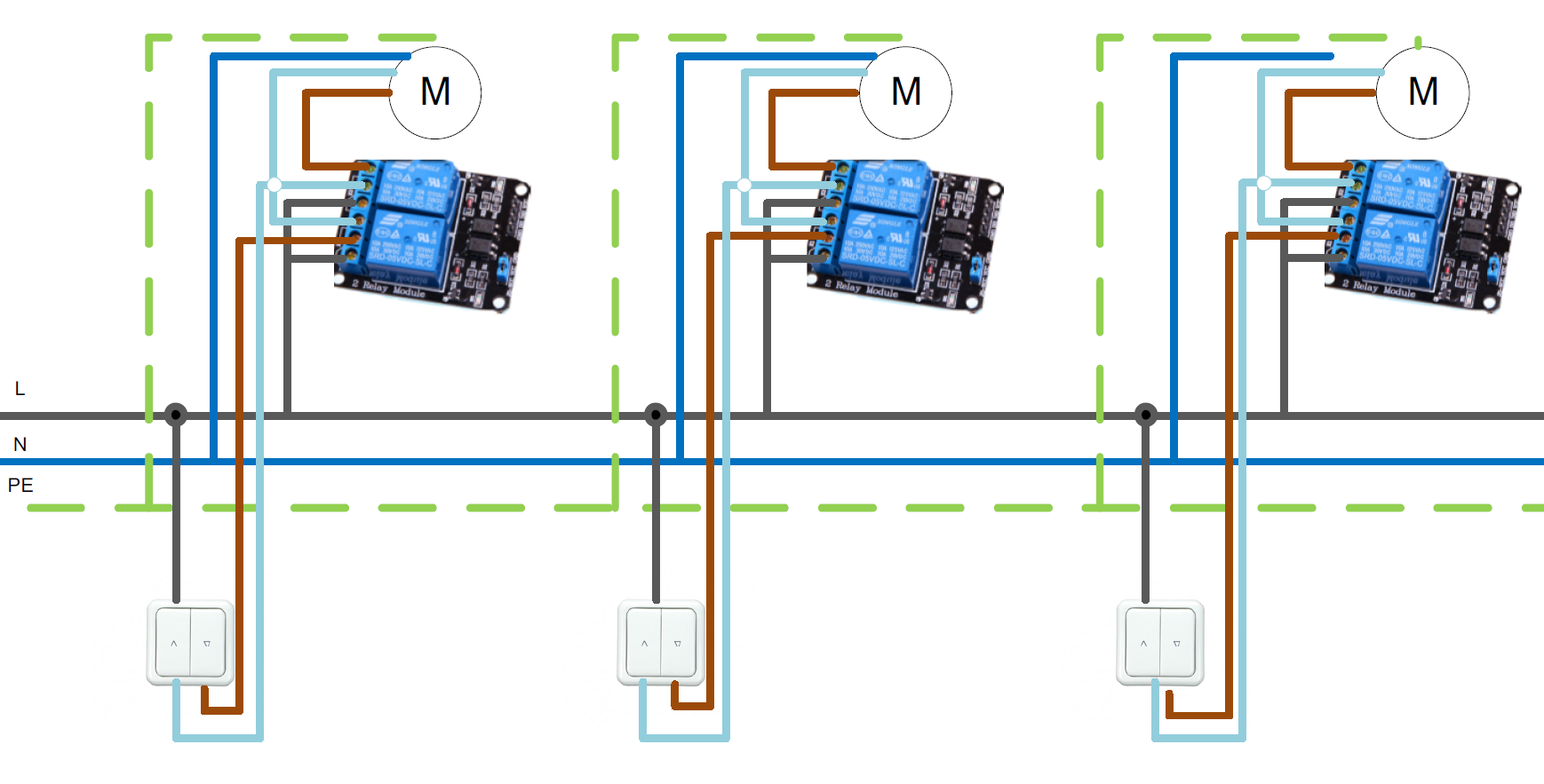
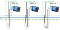
    - i would like the control to be possible using both pushbuttons on the wall and the raspberry, however I would like to prevent short-circuiting or overloading when current is applied to the opposite direction of rotation of the motor. (I have come up with a workaround - please give your opinion - fig.1)
    -I would like to somehow get information through the raspberry when the roller shutter is actuated by a physical button (so I would have control over the position of the roller shutter) - maybe you have some ideas ?

    Lighting control (led tapes and bulbs) I would like to do on relays (available with optoisolation protection on a popular auction site) here also a similar question arises - how to determine the current state of the bulb (on/off) so that it would be possible to control with wall switches at the same time ?
    Is it possible to solve this on standard wall switches, or do we need bell switches and bistable relays?

    For controlling the radio in the bathroom I would like to use a dedicated LCD display - Link , however I don't know if it is possible to place it at a distance (about 5-6 metres) from the Raspberry PI ?

    I will add further problems and ideas as the project develops.

    Thank you and best regards,
    Paul
    Raspberry PI - Home automation: Control of roller shutters, light, temperature and audio
  • ADVERTISEMENT
  • #2 14566271
    bi3dron
    Level 18  
    Posts: 254
    Help: 24
    Rate: 22
    If you design the circuit well (hardware and software) then I think you could dispense with the manual/tiny control. You can always run all the cables to a single point and leave some small provisions there, then even from such a tiny one you will be able to convert everything to manual control without forging in the walls (just have to remember to have enough space).

    But as I write this post I am getting more ideas :P

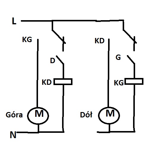
    As protection for the roller shutters in the switchboard it is with NO-NC relays that you use a small safety loop (fig.1).
    Legend:
    KG, KD - relay (monostable) up/down (contacts and coils)
    G, D - keys for up/down control (in parallel to these you can add relays controlled by the raspberryPI).
    Raspberry PI - Home automation: Control of roller shutters, light, temperature and audio
    As for getting information to the rPI about manual activation of the roller shutters - you add another relay in parallel to the one from the roller shutter, which makes a shorted contact for the rPI (unless you are using contactors - then you only need an auxiliary contact).

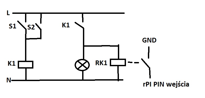
    As for lighting - bell and bistable. Except that in order for the rPI to have information about whether the light is on, you will get this with the following drawing:
    Raspberry PI - Home automation: Control of roller shutters, light, temperature and audio

    Legend:
    S1 - bell button by the door
    S2 - bedside bell button
    K1 - lighting relay (bistable)
    rK1 - relay for feeding information to rPI (monostable) (makes contact for rPI input, I don't know if by shorting to ground, I used the arduino :P )

    And here, of course, you can also insert in parallel to S1 a relay from rPI (monostable e.g. for 1/2sec switched on e.g. for control via WWW/bluetooth etc).

    As for the display - I think it shouldn't be too much of a problem to even let it run on a twisted pair - IMO it will work.

    Only with the above junctions you lose such possibilities as e.g. distinguishing between long and short key presses etc.
  • #3 14569667
    pawel1392
    Level 13  
    Posts: 141
    Rate: 17
    Hello,
    I've checked and unfortunately the display doesn't work on the long wire - I've done a bit of reading and the SPI interface won't pull it off and the display uses that interface - fortunately I already have an idea to get around this (cheapest tablet).
    I came up with a slightly different idea for the lighting control :
    Instead of putting voltage through a physical switch, you could put a signal through it for the rapberry, which would in turn control a relay, and one relay would suffice, and we would have information about the current state - what do you think ?
    best regards,
    Paul
  • #4 14573070
    bi3dron
    Level 18  
    Posts: 254
    Help: 24
    Rate: 22
    Generally this is how most installations in intelligent buildings (which are based on wired installation with a central unit-brain) work :D
    I presented you with the solution you would like to have done (rPI fail-safe or something), and since it's "only" a flat (only compared to at least a two-storey detached house), the cost would not be super special either. ;)

    As far as the selection of switches is concerned - I recommend monostable (bell) switches - the problem of anticipating a multitude of scenarios with several switches in a room + remote control + schedules etc. is eliminated.
  • ADVERTISEMENT
  • #5 14613480
    pawel1392
    Level 13  
    Posts: 141
    Rate: 17
    What type of relays should I use?
    I think 05V and activated by a high signal (High level active) am I right?
  • ADVERTISEMENT
  • #6 14622591
    bi3dron
    Level 18  
    Posts: 254
    Help: 24
    Rate: 22
    Relays have 2 basic components (it's basically one device, but still):
    - coil (i.e. you look at what voltage and current draw)
    - the contact (type (NO/NC, mono/bi-stable), load capacity)

    At the rPI, check what the maximum current capacity of one output is and then select the relays; or look around for ready-made ones for the bus.
  • #7 16580871
    leonarsen
    Level 2  
    Posts: 4
    Have you already thought about what temperature sensors you will use? How many measuring points do you want to make? What distances from the measuring point to the raspbery?
    Greetings :)
  • ADVERTISEMENT
  • #8 16602182
    cP1us
    Level 9  
    Posts: 40
    I am currently doing something similar. There is a ready-made Linux system for Raspberry PI or a Linux service called OpenHab (it has an http server, is based on Eclipse SmartHome, the rules themselves are programmed in a scripting language). The whole project is open source, there is quite a community for it. You also have ready-made plug-ins for Open Hab with weather etc, which you can program in the style of turning on the irrigation for 5 min if the air temperature is 10 degrees and it's raining, and for 15 min if it's 30 degrees. There is also an Android app that allows you to control the system, or you simply connect via HTTP to a local server. People install relays wirelessly or via an internet cable
  • #9 16605348
    ditomek
    Level 22  
    Posts: 590
    Help: 24
    Rate: 230
    The Raspbery Pi is just over 20 IO pins. You haven't written how many of these devices you would like to control and how this is to be done. Are the switches and relays controlling the receivers to be connected to the raspberry, or is it to be connected in some other way? Then all the fun will end up in one room. Sticking to this topology, you will end up having to solve the problem of the amount of IO needed to serve all the points.
  • #10 16610501
    cP1us
    Level 9  
    Posts: 40
    A bit of an offtopic since the topic is 3 years old, I just added to the topic that someone looking for a solution for this type of system then raspberry pi + openhab is a good option

    As for the pin limit you are not limited because:
    - there are port expanders (then the ports are probably unlimited)
    - some devices can be connected directly to the router via ethernet cable
    - you can also connect them via wifi
  • #11 16610636
    PiotrPitucha
    Level 34  
    Posts: 2658
    Help: 201
    Rate: 423
    Hello
    The number of ports is not unlimited, using publicly available parts you can reach almost 400, 128+128+64+64+64+64+classic ports with GPIO malinka to be exact.
    Where does this come from?
    We have Microchip chips with 16 bit ports after SPI, addressed with three bits, making 128 pins.
    The next Microchip available after I2C 16 bit with three bit addresses, another 128 pins.
    the 8574 gives us 8 bits and also three bits of address which gives us 64 pins after I2C.
    the 8574A gives us 8 bits and also three bits of address which gives us 64 pins over I2C.
    I don't know of any others readily available that don't conflict with the address, but the number is still impressive.
    Plus you can control dozens of devices over CAN or other such inventions.
    Greetings
  • #12 16610721
    ditomek
    Level 22  
    Posts: 590
    Help: 24
    Rate: 230
    Fact: March 2015.
    You write to me about limitations and these comments were me directing to the author of the post. I personally know how to deal with them.
    For my part, that is all.
    Regards.
ADVERTISEMENT