logo elektroda
logo elektroda
X
logo elektroda

Troubleshooting Crawford ECS930A + CDM9 Automation Drive: Motor Not Responding

lz11980 50028 60
ADVERTISEMENT
Treść została przetłumaczona polish » english Zobacz oryginalną wersję tematu
  • #31 20482483
    jamaika111
    Level 2  
    Hello,

    I was reading the whole conversation because I have a problem with the esc 950 too.
    The motor isn't doing anything, I can try up / down with the keys or programming mode or the wireless transmitter nothing happens.

    After following the troubleshooting guide I'm pretty sure that there is a problem with the 24V AC and DC power.
    I have 24V AC between x1:6 and x1:7, but only 15V AC between x1:7 and x1:9. The guide says replace the manouvring card which makes no sense because the power comes from the motor....

    And the second problem is that I have no 24V between x1:7 and x1:5, so the security receiver from the bottom lip has no power which results in an E04...

    Has anybody an idea?

    Best regards
  • ADVERTISEMENT
  • #32 20482536
    doortech
    Level 9  
    Replace maneuvering card. There is a short in one of the components.
  • #33 20482636
    jamaika111
    Level 2  
    Thanks for your reply, but I don't think that's a problem on the maneuvering card.

    There are only diodes, resistors and capacitors, I checked them they were fine.

    I also unplugged the maneuvering card and there is still only 15V coming from the motor unit.
  • #34 20482698
    doortech
    Level 9  
    Have you measured that rail on the cards in the motor?
  • ADVERTISEMENT
  • #35 20487100
    jamaika111
    Level 2  
    Yes I measured all the rails (so far as possible) without any findings.

    I'm wondering where the power gets lost.... Which device is responsible to convert the 24V AC to 24V DC on the processor card or power card? There must be the problem, because I have only 15V between X1:7 and X1:5.
  • #36 20487471
    doortech
    Level 9  
    Disconnect everything from the rail, and measure power isolated from everything else.
    This means no controller card connected on the controller side. The plug should easily lift off. Then measure it.

    If the rail is still low, then you have a problem of delivery from the motor unit.

    If it measures correctly, you have a faulty component in the controller, likely a condenser or resistor shorted to ground.
  • #37 20489531
    jamaika111
    Level 2  
    Yesterday I disconnected everything from the processor card in the motor unit (I did the tests with and without the power card) only the two wires for the 230V input were connected. Exactly the same result when connecting everything:

    Between X1:6 and X1:7 24V AC
    Between X1:7 and X1:9 13V AC ??
    Between X1:7 and X1:10 not possible I only have 9 pins
    Between X1:7 and X1:2 no power
    Between X1:7 and X1:12 not possible I only have 9 pins
    Between X1:7 and X1:5 no AC or DC power

    I am pretty sure the problem is a minor little component... Investing 800€ in a new processor card is no option :(
  • ADVERTISEMENT
  • #38 20489849
    doortech
    Level 9  
    jamaika111 wrote:
    Yesterday I disconnected everything from the processor card in the motor unit (I did the tests with and without the power card) only the two wires for the 230V input were connected. Exactly the same result when connecting everything:

    Between X1:6 and X1:7 24V AC
    Between X1:7 and X1:9 13V AC ??
    Between X1:7 and X1:10 not possible I only have 9 pins
    Between X1:7 and X1:2 no power
    Between X1:7 and X1:12 not possible I only have 9 pins
    Between X1:7 and X1:5 no AC or DC power

    I am pretty sure the problem is a minor little component... Investing 800€ in a new processor card is no option :(


    Then you have a short to ground on one or more components in the motor card.
  • #39 20764055
    rajbesam
    Level 1  

    >>16194578
    Hi sir, how to clear the error code E04?
  • #40 20816930
    michaelsteiness
    Level 2  

    I just want to know about the programming.
    It says push stop. Is that the emergency stop? Because I only have up, down, and emergency.

    Added after 2 [minutes]:

    I just want to know about the programming.
    It says push stop. Is that the emergency stop? Because I only have up, down, and emergency.
  • #41 20820054
    TomcioK
    Level 10  
    >>19937305 .
    Hello everyone.
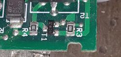
    I have a question. What is the component in the top left corner? C603. In the gate I have, it is damaged and signed as GP137. However, I cannot find it either. I would be very grateful for help.

    Close-up of a circuit board with a component labeled C603 in the top left corner.
  • #43 20822128
    TomcioK
    Level 10  

    Thank you very much. I still have this question. I am just learning electronics, there are a lot of electronic components signed with some designation. Which cannot be found anywhere. And with the schematic is also a problem. From kond you know that it is Transil 6.8V, SM6T6V8A. This is years of practice or are there any books with the markings of this?
  • #45 21306286
    krisczrn
    Level 11  
    Hello,
    I am refreshing the topic because I have received such a gate drive but without a controller - just the motor. Is it possible to connect it "rigidly" by simply feeding a 230v remote control to the motor, directing the drive up and down?
    Regards
  • #46 21306408
    doortech
    Level 9  
    Sure, but not really. You have to modify the motor a lot, and the gearbox will not like the rest of its life.
  • #47 21417794
    robertsjolin
    Level 3  
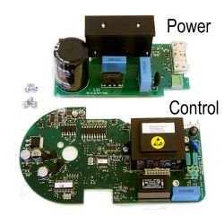
    Does anyone know if this PCB is plug and play or it needs to be programmed?
    Two printed circuit boards labeled Power and Control.
  • ADVERTISEMENT
  • #49 21417800
    robertsjolin
    Level 3  
    >>21417797

    Thanks for answering, with program tool?
  • #51 21422396
    robertsjolin
    Level 3  
    >>21417822
    @doortech
    Thanks, can I make all the programming myself or do I need a professional technician from Assa Abloy / Crawford to complete it?
  • #52 21425113
    doortech
    Level 9  
    >>21422396

    You can do it yourself. It’s relatively easy. Instead of the ground switch, squeeze the bottom safety edge shortly. You’ll see it in the documentation as well.
  • #53 21426667
    robertsjolin
    Level 3  
    >>21425113

    Thank you for your support!
  • #54 21456159
    tomek1989549
    Level 4  
    Welcome!

    I am refreshing the topic of the ECS930A CDM9 controller. The gate works as it should after programming the road, except that the display shows 112 and the service light is on. Despite this, the gate works until I disconnect the power, then E24 is displayed and the gate loses these road settings and has to be programmed from scratch.
    Is it possible to upload a different batch that will help?
  • #55 21458691
    Przemek200
    Level 2  
    112 is the number of cycles made by the door. Error E24 is the correct behaviour after a power failure. The gate does not know what position it is in. Press the open button, the gate will open fully, stop at the buffers and go into normal operation. The service light can be switched off using the programmer.
  • #56 21458967
    tomek1989549
    Level 4  
    In my case, after switching on the power supply, the door opens to the buffers when I press the open button once, while downwards it works in a pulsating manner, i.e. I have to keep the close button pressed the whole time, only after re-training the door can close again without constantly holding the button, just one click and everything flies out of the machine, and the same with opening once and the door rises by itself. I don't know if one of the dip-buttons is responsible for this or if they have no influence?
  • #57 21459235
    doortech
    Level 9  
    tomek1989549 wrote:
    In my case, after switching on the power supply, the door opens to the buffers when I press the open button once, while downwards it works in a pulsating manner, i.e. I have to keep the close button pressed the whole time, only after re-training the door can close again without constantly holding the button, just one click and everything flies out of the machine, and the same with opening once and the door rises by itself. I don't know if one of the dip-buttons is responsible for this or if they have no influence?


    Then there is some kind of error/fault with your safety edge/PNE edge. You should investigate further. Maybe calibrate your PNE switch.

    To calibrate the switch for a ECS9 series controller, you disconnect the switch, OHM it with a multimeter, and carefully turn the lead screw on the switch until it stops beeping, then turning the screw back one half turn so that the multimeter beeps again.
  • #58 21464659
    tomek1989549
    Level 4  
    Gentlemen, how can the auto-close be deactivated on this control panel? The auto-closing starts somewhere after about 1 minute, while the door is open all the way up and the stop button is not pressed.
  • #59 21464696
    Przemek200
    Level 2  
    >>21464659 .

    Depending on the software your control panel has, a dot may flash in the lower right-hand corner of the display to indicate an active automatic shutdown. Press and hold STOP, while still holding down STOP, press the "up" and "down" buttons at the same time, keep these three buttons pressed for about 6 seconds and release, the dot should disappear and the automatic closing will disengage.
  • #60 21468799
    tomek1989549
    Level 4  
    Hello!
    I have a control panel ECS940A. This control panel has a pneumatic switch. I wanted to know if it is possible to replace this switch and plug in the optosensors. I would just like to add that there are 2 centimetre holes in the safety strip, and the ones I have been able to find online are 12 mm. Is there a ready made kit or do I need to rework this somehow? I also need wiring diagrams.

Topic summary

The discussion centers on troubleshooting the Crawford ECS930A gate automation system with the CDM9 drive, focusing on a motor that fails to respond to control inputs. Key issues include non-responsive motor movement despite pressing up/down buttons, blinking red RXD and TXD LEDs on the inverter board, and sensor-related complications such as the drive disengagement magnetic sensor (hall sensor) affecting motor operation. Users detailed the process of removing the inverter board, checking potentiometers T1 and T2 (auto-closing time and lamp lighting), verifying jumpers (notably between pins 9-10), and examining pneumatic and photocell sensors. Problems with power supply voltages, error codes (E04, E08, E14, E24), and capacitor failures on the inverter board were also discussed. Solutions involved replacing electrolytic capacitors, recalibrating pneumatic safety edges, and programming the control unit via SW1 and DIP switches. The motor is a three-phase type powered by a 230V supply converted by the inverter. Direction of rotation adjustments require rewiring due to lack of official documentation from Crawford. Programming and error reset require proprietary tools, though some users shared step-by-step programming instructions. The discussion also touched on replacing pneumatic switches with optosensors, with recommendations against it due to controller compatibility. Overall, the troubleshooting process involves detailed electrical measurements, sensor verification, mechanical disassembly, and firmware programming to restore proper motor function and gate operation.
Summary generated by the language model.
ADVERTISEMENT