logo elektroda
logo elektroda
X
logo elektroda

Homemade method of measuring earth resistance

kortyleski 92295 46
ADVERTISEMENT
Treść została przetłumaczona polish » english Zobacz oryginalną wersję tematu
  • #31 19039567
    slim24
    Level 12  
    This terminology blows me up. From the meter I have 5x16 led to the switching station, but the protective one is not connected to anything. In the switchgear, the blue one is introduced to the main disconnector, then it goes to 4 differentials. The AN coming from the differentials are separated into 4 separate buses that connect only those circuits protected by a given differential. And the PE rail is one and it is connected with all the evidence and the strip footing. I repeat once again that when I had the fifth protective one connected to the PE TO busbar the differentials did not work, because in the box with the meter the neutral is grounded.
  • ADVERTISEMENT
  • #32 19039585
    kozi966
    Moderator of Electricians group
    Leave those differentials alone, man.
    You write that you have a TN-CS chip, but in fact you made a TT chip.

    It results directly from this:
    slim24 wrote:
    but protective, not attached to anything.

    slim24 wrote:
    the blue one is introduced into the main switch


    You don't understand that in the TN-CS system, the PEN conductor should first go over the PE rail or the PEN rail. And this rail should also have a connection to the N rail.
    In this case, the disconnector means that you do not have a PEN conductor, you also do not have a PE conductor (because it is not connected), so you also do not have a metallic short-circuit loop.

    The surveyor is right.

    By the way, the operation of the differentials has nothing to do with it. They do not have to (although they can) operate from shorting the PE and N conductors and this is normal (!).
  • ADVERTISEMENT
  • #33 19039601
    slim24
    Level 12  
    Electrician With the meter is an employee at the guest who is authorized to perform measurements and issue reports. He was so oriented that he himself did not know that something was wrong. He just walked through all the nests in the house and wrote down the results in his notebook. I found out about the irregularities by phone from the electrician who sent the employee. I did the installation myself.
  • #34 19039607
    kkas12
    Level 43  
    And this blue vein is broken by a disconnector. For what?
    And it is not N but PEN since the green and yellow wire is free.
    And whoever interrupts this mind, firstly, and secondly, since the green-yellow wire is hanging in the air, the guest has measured the ground impedance.

    This four-way WG should be deleted, replacing it with a three-way one, then the blue PEN conductor should be connected to the grounded PE bus, which should be connected to the N bus.
    And then repeat the SWZ measurement, starting from the PE rail in the table.


    slim24 wrote:
    I repeat once again that when I had the fifth protective one connected to the PE TO busbar the differentials did not work, because in the box with the meter the neutral is grounded.
    This is buttery butter and I suggest not to deal with it, not to deal with it at this stage.
    First, you need to bring the connections to the standards-compliant state.
  • ADVERTISEMENT
  • #35 19039711
    slim24
    Level 12  
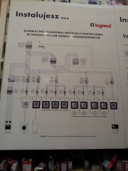
    Then I misunderstood it myself and thought it was TN-CS. I was building an installation based on this scheme.
    Homemade method of measuring earth resistance .
    I thought N had no right to meet PE in this switchboard anymore. I am supposed to understand it so that this bench grounds it sufficiently only I have it badly connected?
  • #36 19039732
    kozi966
    Moderator of Electricians group
    This is a TN-S installation diagram, and incorrect. And you forgot about that PE. The PE in this drawing would start in your situation with a PEN wire that you did not connect properly.
  • #37 19039760
    kkas12
    Level 43  
    In a TN-C system (if you are actually dealing with it) there is no such thing as "sufficient grounding".
    The foundation earth electrode is an equalizing earth electrode and the resistance of such earth electrode is irrelevant for the protection against electric shock.
    If, however, you had a lightning protection system, then its grounding resistance should not exceed 10 ohms.

    If the division of PEN takes place in the junction, under no circumstances can PE and N join again in the table.
    However, such a division in the connector distant from the building does not make any sense and in unfavorable circumstances (loss of the continuity of the N wire) brings measurable financial losses, because in this case, 400V voltage may appear on the terminals of single-phase receivers, which will definitely lead to their damage.
    Today, energy suppliers even make it impossible to connect the fifth wire in the meter cabinet.


    PS
    I will never understand you laymen who, having no knowledge, do the installation themselves. And then you make begging posts for help.
    Understand that no one will forbid you to install it yourself in your home, just for God's sake ask before starting work. Life will then turn out to be much simpler and easier because you will avoid problems that you create yourself,
  • ADVERTISEMENT
  • #38 19044194
    slim24
    Level 12  
    I understand my mistake, it will be corrected. In my installation, the PEN distribution point followed the meter in the switching station at the border and there were 5 terminals: L1, L2, L3, N and PE. I did not fully understand how the RCDs were supposed to work and therefore I disconnected the PE from my ground bus and the TT actually came out, but nobody lost their life because of it, only the measurements did not come out. I just do not understand what these unfavorable conditions may cause the loss of N continuity in a cable buried 1m underground. And I will not give up the 4P disconnector, because it is a network / generator switch. And after starting the aggregate, no pole with the external network should rather have a tangent point.

    Ps. The fact that someone did not finish their studies in electricity does not mean that he is a fool and he will not put cables on the walls. It is best to recommend it to others and go back in development yourself. And so at least a person learns something. And if someone does not want to help on the forum, I do not force anyone to sign. And to those who helped to understand my mistake, thank you very much.
  • #39 19044212
    kkas12
    Level 43  
    slim24 wrote:
    And after starting the aggregate, no pole with the external network should rather have a tangent point.
    Don't overdo it, buddy. In the TN-C system, the PEN conductor is a protective-neutral and additionally grounded conductor. So, by the way, you'll practically never eliminate this "tangent point".
    As for these "unfavorable conditions", read this:

    Link
  • #40 19044295
    adwlodar
    Level 28  
    slim24 wrote:
    And I will not give up the 4P disconnector, because it is a network / generator switch.

    Can you provide the model of this switch out of curiosity?
    slim24 wrote:
    And so at least a person learns something

    I "admire" you a little ... Without basic knowledge about the installations, you have made one at your place and you have also added such a sensitive topic as power supply from a generator. Do you already have some aggregate purchased?
  • #41 19044335
    slim24
    Level 12  
    I think that I have the basic knowledge. In my youth, I wanted to become an electronics engineer, but I didn't get into school. I have always been more oriented in direct currents. At the time when I was doing the installation, I had SEP qualifications up to 1KV and since I do not work in the profession, I did not renew it.
    https://allegro.pl/oferta/hager-przelacznik-siec-agregat-1-0-2-4p-40a-sft440-8858346660? I have.
  • #43 19311978
    esox53
    Level 11  
    What is a band around the building for? In order that all elements of the building have the same potential, because there are different potentials in the ground depending on the conditions in the ground and the distance to the ground of the transformer supplying the facility. If we connect the earthing of the building on the PEN rail with the N conductor of the transformer, we will reduce both of these earthing to one potential. The point is that touching the N conductor in a building that has no grounding, we can feel the current when touched by a hand, because the building potential will be different from the transformer's zero point potential (including its earth electrode). In this case, by touching the pin in the socket, we can activate the residual current circuit breaker, because there is too much voltage between the transformer ground and the socket pin and the current flows through the human (sometimes too high). Too much distance and ground resistance can have a large effect on the effectiveness of the RCD. In addition, the ground on which we stand or footwear impede the effective flow of the current, i.e. the one that will cause the residual current circuit breaker to trip. Therefore, the building and all its equipment (bathtubs, showers, household appliances) should have the same potential to make the protection against electric shock more effective. In the absence of an earth electrode around the building, the PE and N conductors can be simply dangerous, this is rare, but it does.

    Added after 7 [minutes]:

    And this Hager switch is suitable for a generator in the building, as long as it does not give voltage to the meter.
  • #44 19312019
    kkas12
    Level 43  
    esox53 wrote:
    In this case, touching the pin in the socket can cause the residual current circuit breaker to trip ...
    By what miracle ???
    esox53 wrote:
    Therefore, the building and all its equipment (bathtubs, showers, household appliances) should have the same potential to make the protection against electric shock more effective.
    There are still no metal windows and metal frames.
    These are heresies my dear friend.
    Heresy!
  • #45 19322378
    kortyleski
    Level 43  
    And it turns out that a herd of parasites fell into my topic, therefore the topic was blurred. From a certain point imposed by me, the topic concerned only TT.
    Well, the installation is completely new and properly secured. Except for one cable for the garage, which should have a slightly larger cross-section. But it will stay that way for now.
  • #46 19323351
    retrofood
    VIP Meritorious for electroda.pl
    kortyleski wrote:
    And it turns out that a herd of parasites fell into my topic, therefore the topic was blurred.

    Then why didn't you lock him up? Or write to mods to clean them from accretions.
  • #47 20223358
    Sintesi
    Level 11  
    As for the possible cases of N loss in the network, we can give an example when the gentlemen from Enea replaced a transformer in my area. After turning on the power, it turned out that they did not connect N. Effect? More than a dozen houses with fried household appliances, automatics, stoves, computers. For me, a miracle without major failures (blown fuse on the CO stove and transformer power supply for computer speakers) because the surge arresters (OBO) worked. They were terribly sooty. A neighbor standing in the kitchen suddenly saw smoke rising from the espresso machine, even though she was not making coffee. The costs for ENEA were considerable ...

Topic summary

The discussion revolves around methods for measuring earth resistance in home electrical installations without specialized equipment. Various approaches are suggested, including using an ammeter and voltmeter with a load, and connecting a light bulb to check the earth electrode. Participants emphasize the importance of understanding the distribution network type (TN-C, TN-S, TT) and the implications for grounding resistance values. Recommendations for acceptable resistance values are provided, with a focus on ensuring safety and compliance with standards. The conversation also touches on the significance of proper connections and the potential risks associated with incorrect grounding practices.
Summary generated by the language model.
ADVERTISEMENT