Hello.
Before buying, it is worth checking what version we are dealing with.
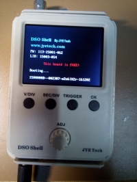
The point is whether the version is original or not. If we have non-original versions, after the update you will see the message: This board is Fake!
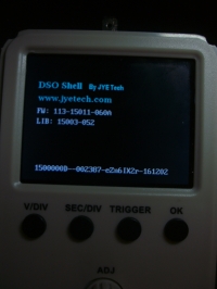
This applies to the version with the serial number shown in the picture.
Fortunately, there is an update that eliminates this problem. In the file
DSO150 Modification of software and hardware.zip is an appropriate hex
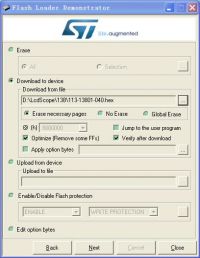
I attach instructions on how to and how to do it. Description in PDF
There is a description of the modification in the file but I did not do it for those moments.
Watch out for pads and power supply socket because it is very delicate.
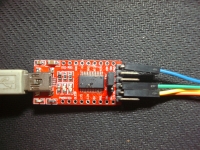
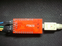
On FTDI232 It should be switched to 3.3V !!!!!!!!!!!!!!!!!!!!!
Bought my DSO150 from ebay (Original), and it worked good but after upgrading it from 113-15001-055 to 113-15001-064
im getting error stating "This board is FAKE !" and stuck at this screen.
update:
I have got back reply from seller and they sent me link to wifi drivers ? ?wtf -complain is in order...
Clearly seller have no clue what firmware is or he have just to many items to control (4000)
so getting help from ebay seller is unlikely, and then i found your link that helped a lot.
file 113-15011-060A got errors away.
I have to try to read the firmware with the help of the application given in the pdf in the first post - the option Upload from device. If it was possible to read correctly from the DSO firmware, you can try to throw in other files and if you do not succeed, return to the original. Maybe someone with more experience with STM32 will say something more about its programming with the bootloader with the help of this or another application. I have little time but I have to motivate because in case of damage I can try to give away the warranty device and it would be nice to have the latest firmware.
Here and there is a problem because in my case the return to the original was impossible. Oscilloscope graciously informed. This board is FAKE! This version which I made fortunately was not blocked.
Here and there is a problem because in my case the return to the original was impossible. Oscilloscope graciously informed. This board is FAKE!
After such a message was "blocked" the bootloader? This is important information for me, because if so it will be possible to update only to your version of the software. I mean programming options from the STM application provided in pdf.
Read my post carefully and you'll understand what's going on. You can always update !!! What's your serial number? The serial number should be on the plate sticker.
In fact, with this update I got caught, but that's because I'm currently working on another project and the processors have been dying. On this sticker with a bar code I have: H2uCu2av I take for completing the software and hardware to make this upgrade. _______ And the first zonk - Clear the flash that is, I will not have a copy to return to the original firmware, but whether the bootloader will be?
For now, I gave up the firmware updates because I have a more diligent job. By accident, I came across this link if I find a slower time after looking.
Please, make a conversion of the latest firmware 113-15001-110 so that it doesn't show the "fake" message. Two many people got scammed and bought "fake" versions of the DSO150 and now they cannot update missing all the improvements new versions bring.
I ve already read the pdf, i can Flash files, and reading but i Need a full hex Dump. my Bootloader is gone.
Device is in reboot loop, because i did a mistake (erased full 64k)
That´s why i Need an 64k Dump file.
Are they paying back the money on aliexpres if we buy at the auction described as original and send us the counterfeit that is functioning until the update? Are there any problems with that? Because a referral is a cost like this device.
Can anyone help me. I updated my unit to the latest firmware and the device said it was a fake board then the screen went white. I tried reflashing the firmware with this one and I still only get a white screen. I have unsoldered the jp1 and jp2.
To unbrick your fake DSO150, stuck on the white screen, you have to re-enable the WDG_SW byte.
- download the michar71's Open-DSO-150 version (thank you man, you saved my DSO!)
- flash it with Flash Bootloader Demonstrator
- once done, start Flash Bootloader Demonstrator again
- at the page where you normally pick a file, click at 'edit option bytes'
- enable WDG_SW checkbox and apply.
Press OK button at the first restart to reset to default.
You can also install the current firmware on FAKE boards.
Read only to the end !!
Method: 1. Download the firmware hex file from jyetech https://jyetech.com/firmware-dso-150-shell/ 2.Download Hex2bin converter from Sourceforge https://sourceforge.net/projects/hex2bin/ 3. Copy the hexfile into the folder of the hex2bin.exe file 4. Convert the hex file into a bin file - command line hex2bin.exe 113-15001-120.hex 5. Search for the branded serial numbers in the generated bin file, change them (eZn6IX2r, t2uvGy8a) and save the changes 6. Transfer the bin file with the STM32 Flash loader as already described
Now the DSO150 starts with the new firmware without the note that it is a fakeboard.
Problem: There is another security limit. This shows that after a while the rotary control no longer works. An activation code must be entered. You have to inquire about this at jyetech. But for a fakeboard they probably won't calculate that. The code has 4 digits, but includes the hex range. This results in 65536 possible combinations. I had looked at some BoardID code combinations, but I couldn't decipher them. I found the combinations on the Internet or asked for the code for known IDs. There must also be a check digit in the board ID, since any ID was acknowledged with the answer that this ID does not exist (I have incremented the last digit of a known code).
Reading is not always stable however (there is a note saying that two SMD components should be removed from the PICKIT3 - TR3 and R50). There are also users who can read them out without removing these components.
Unfortunately I did not get a connection to the 24LC. I don't want to remove those little parts either, as I'm not sure I can get these back on
I would say that the activation code is checked in the following part of the code. Unfortunately, my knowledge is too thin to understand what is being done here.
Unfortunately, I wrecked my DSO150 yesterday.
Well no matter.
Here again my findings.
I have graphed my known Serials (converted from Ascii to Dec and summed) and Codes (Hex to Dec). After that, the code increases with increasing serial.
For the serial t2uvGy8a I would still have a range of 11037 codes (which is between my known codes).
I suspect the serial is one of the following (assuming my graphical approach is correct):
- B4A0
- B4A1
- B4A2
- B4A3
- B4A4
- B4A5
- B4A6
- B4A7
- B4A8
- B4A9
- B4AA
- B4AB
- B4AC
- B4AD
- B4AE
- B4AF
- B4B0
- B4B1
- B4B2
- B4B3
- B4B4
I also tried to read out the EEPROM again. So it works very well: https://arduino-projekte.webnode.at/meine-projekte/eeprom-monitor/ Unfortunately, in the installed state (here I used a level shifter because the Arduino works with 5V), contact with the EEPROM only occurs briefly during the boot process (the microcontroller then presumably pulls the data pins to GND).
Unfortunately, not only the microcontroller died on my board, but apparently also the EEPROM, because I can no longer access it even after unsoldering it.
Oh yes, after successful activation only one bit in the EEPROM has to be changed, because the guys from JYETECH said that activation is only necessary once. If you know the place, then it should be "easy" to write a program that sets this bit.
Maybe you should also get rid of the original firmware. On the one hand there is the project from Michar71 https://github.com/michar71/Open-DSO-150 but it doesn't seem to go any further and there are no ready-compiled files
- Assignment of the rotary encoder signals to separate pins. In the original, the encoder has to share the interrupts with the display, which means that pulses are often lost.
- Activation of the USB interface. The STM32F103 has a USB interface that can be used to control and read out the data.
- Replacing the processor with a GD32F303. This speeds up the program considerably.
If you want to patch your DIY DSO150 to the actual firmware 113-15001-120 [ 2018.06.05 ] I have 2 patches for you on the original jyetech firmware.
1. download the firmware from jyetech
2. extract the hex file
3. use a text editor to edit the hex file
4. patch1 disable fake serial number check (this changes the 2 fake serial numbers in the flash to fZn6IX2r,u2uvGy8a)
change the file line number 2954
from :10B880004F205368656C6C00655A6E3649583272A9 to :10B880004F205368656C6C00665A6E3649583272A8 change the file line number 2955
from :10B8900000743275764779386100000000000000BE to :10B8900000753275764779386100000000000000BD
5. patch 2 disable the required activation code. This changes the ARM branch instruction BEQ to BNE and invert the test of the right unlock code
change line 1616
from :1064E000063013D0214C63895A1C022B62810AD8D2 to :1064E000063013D1214C63895A1C022B62810AD8D1
6. save the hex file
7. follow the normal firmware update procedure as described on jyetech with your patched hex file
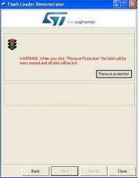
8. be not afraid if the ST firmware tool reports a protected flash and you have to acknowledge a mass erase. The bootloader of ST is in the ROM and is not touched by this procedure. So if something goes wrong you can always restart a new flash operation
9. unsolder the JP1 and JP2 and reassemble your DSO150 and have fun
I confirm the effectiveness of the boyak75 method. It's been a long time since I had so much fun editing .hex in "notepad". Thank you and best regards.
Hello all, I think this is my first post here.
Many thanks to brottoaster and boyak75 for their research!
Like t161, I've tried boyak75 patches on FW 120 and they work OK: It doesn't detect my fake serial (eZn6IX2r) as such (1st patch) and accepts any random activation code (2nd patch).
I've also tried the first patch only and then activating with the code generated by his keygen (8CED), and it also worked.
But, in both cases, a problem remains: Every time I restart the scope I have to introduce the unlocking code again (random if two patches are applied or 8CED if only the first one was applied). It seems like the supposed unlocking bit in the EEPROM mentioned by brottoaster in his last post is not correctly set...
With this idea in mind, I also tried to read the EEPROM, but it's apparently empty (by the way, also tried it in an unlocked genuine DSO138mini that I have with the same results), so I thought either I was not reading it OK (I'm using a CH341A programmer with the EEPROM unsoldered from the scopes, and it works OK with other 24LCXX EEPROMs, so I don't think that's the problem), or, maybe, the supposed unlocking bit wasn't stored there.
From what I've found, the EEPROM in DSO150 and DSO138mini is not a simple EEPROM but something like a Microchip ATSHA204A CryptoAuthentication device which, apart from an I2C EEPROM, contains a unique serial number and other authentication features, so it's not strange it reads empty with a standard EEPROM reader.
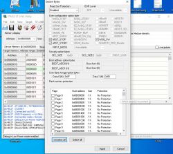
From what I've read in this and other forums, the firmware uses the STM32 option bytes (WDG_SW specifically) to brick the scope when a fake serial number is detected (luckily, it's easy to unbrick it with the programming tool!), so I thought these option bytes might also be used to store the evasive "unlocking bit" and... BINGO!, I could find that the so-called "User data storage option bytes" change when the unlocking code introduction process is completed. Moreover, the content of these bytes coincides with the hex data that appears in the upper right corner of the screen during the boot process (LSB first), but not with the unlocking code. In my case, the "User data storage option bytes" are 0x0F (Data 0) and 0x8D (Data1), the number in the upper left screen is 8D0F and the unlocking code 8CED and serial nº eZn6IX2r, as I said before.
Has anyone experimented the same problem (having to enter the unlock code menu each power cycle)? Can you find any relationship between the serial nº and the number programmed in the option bytes? From videos on the internet and my own scopes, I could find the following data (Scope, firmware version, full 205661-serial nº, unlocking code -from keygen-, boot screen code), but I'm not able to find any relationship:
My fake DSO150 FW120 1500000D-002387-eZn6IXZr-161202, 8CED, 8D0F (0x9341)
My genuine DSO138mini: FW 116, 1380000I-Vm0Qigin, B06F, D56B (0x7789)
Youtuber's DSO150: FW 111, 1500000E-106319-bKPU6V7W- 171129, D058, DD50
Youtuber's DSO150: FW 120, 1500000E2-210374-km0jG5zr-191015, 717D, 5983
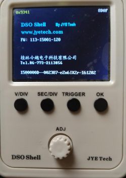
In the two first, I also include (in brackets) another number that appears in the upper left corner of the boot screen if you press the OK key during the boot process (it stops at this screen in this case). I'm attaching a photo of this screen and a screenshot of the STM32 programmer software with the option bytes:
nice to see there are people out in the world using the keygen
The number 0x9341 u see on the upper left side, is the display driver chip of the TFT screen. I guess jyetech has changed the display in the DSO lifetime and therefore the firmware need to know wich hardware revision your DSO. I think that is stored in the option bytes.
I have not looked deep into it and can not say exactly what is stored in the option bytes what in the flash and what in the eeprom.
The things u bring up with your problem that your DSO is not remembering the unlock procedure looks for me like your eeprom is gone.
This explains why u cant read out it and even why your DSO is not remembering the unlock procedure.
Not sure but in case your eeprom is really empty i think the DSO will startup with default values like the reset process pressing 3 seconds sec/div and trigger.
But its not easy to make a good diagnose via remote
The firmware code is written in a simple way and therefore i dont think there is any kind of encription used by jyetech.
I have no ICP header on my DSO and i would need some time to setup all STM stuff on my computer. Just now iam deep into C# projects and have no environment in place for low level. But the idea to do this is interessting because a real debug is much more easier than reading and understanding the code from the FW disassembly.