Hi, boyak75,
Thank you very much for your feedback!
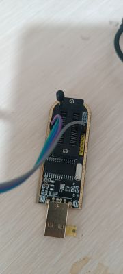
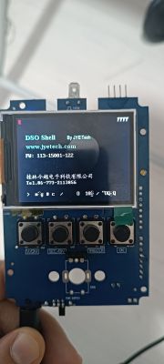
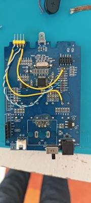
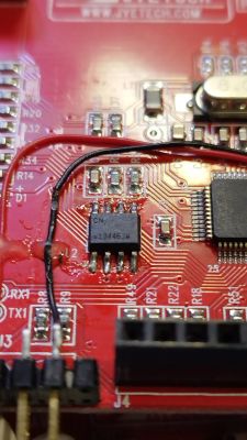
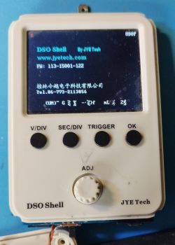
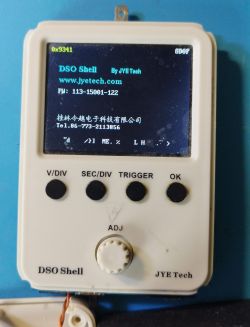
Maybe the EEPROM is really gone... I've done several experiments with both DSO150 (fake) and DSO138mini (genuine), some of which included transplanting the EEPROM between them, to see if this way I could "genuinize" the 150 and update the FW, and maybe in one of these experiments I killed it... Or maybe not, because I'm using a cheap CH341 reader and this could be the cause of not being able to read it. But Brottoaster couldn't read it either (or read it empty), so maybe also it is really like this.
On the other hand, even if it doesn't remember the unlock procedure, it seems to remember other settings (timebase, volts/div...), so maybe these and other data are stored in STM's internal EEPROM rather than the external one, and the external one is only for the CryptoAuthentication device capabilities, as storing the serial nº (but not in the standard I2C EEPROM space).
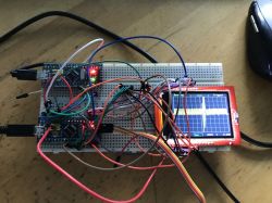
I'm thinking of creating a simple program for the STM to read the EEPROM without the need of an external programmer, or even using this library to fully read the special registers of the ATSHA204A or similar CryptoAuthentication device. I'm not very skilled in programming microcontrollers, but with some luck maybe a bit of modding of the library's examples will suffice... maybe you can distract some time from your project and try this way, but I'll also give it a try
Thanks again and I hope we can make some advances, mostly for curiosity and learning (or just for the sake of it ) as, in practice, I can use the scope as is, just entering the activation menu at the beginning, or going back to 064 version, or using one of the maybe even better open-source FWs out there (or, better yet, buying a "real" scope, there are now good looking units for <200€).
Your posts and Brottoaster's were the first ones I could find with real advances on hacking this thing after some posts about a patched 064 version years ago in a Russian forum (which didn't give many clues on how they were done)
Thank you very much for your feedback!
Maybe the EEPROM is really gone... I've done several experiments with both DSO150 (fake) and DSO138mini (genuine), some of which included transplanting the EEPROM between them, to see if this way I could "genuinize" the 150 and update the FW, and maybe in one of these experiments I killed it... Or maybe not, because I'm using a cheap CH341 reader and this could be the cause of not being able to read it. But Brottoaster couldn't read it either (or read it empty), so maybe also it is really like this.
On the other hand, even if it doesn't remember the unlock procedure, it seems to remember other settings (timebase, volts/div...), so maybe these and other data are stored in STM's internal EEPROM rather than the external one, and the external one is only for the CryptoAuthentication device capabilities, as storing the serial nº (but not in the standard I2C EEPROM space).
I'm thinking of creating a simple program for the STM to read the EEPROM without the need of an external programmer, or even using this library to fully read the special registers of the ATSHA204A or similar CryptoAuthentication device. I'm not very skilled in programming microcontrollers, but with some luck maybe a bit of modding of the library's examples will suffice... maybe you can distract some time from your project and try this way, but I'll also give it a try
Thanks again and I hope we can make some advances, mostly for curiosity and learning (or just for the sake of it
Your posts and Brottoaster's were the first ones I could find with real advances on hacking this thing after some posts about a patched 064 version years ago in a Russian forum (which didn't give many clues on how they were done)


