logo elektroda
logo elektroda
X
logo elektroda

120W induction heater - a typical gadget or a useful workshop tool?

bestler 39771 41
ADVERTISEMENT
Treść została przetłumaczona polish » english Zobacz oryginalną wersję tematu
  • #31 17253533
    _lazor_
    Moderator of Designing
    Well, he cooperates (or rather learn) from a Polish inventor who can do wonders with power supplies. He also does heaters, but mainly power supplies for electron guns and magnetrons (To see a 100kV regulated power supply was something, especially since it wasn't that big).

    I hope that I will be able to praise my toy by the end of the year, whether it is a success when I heat something up, or a show of what it looks like when something goes wrong :D
  • ADVERTISEMENT
  • #32 17253542
    robokop
    VIP Meritorious for electroda.pl
    TechEkspert wrote:
    For me, all this induction heating is black magic, see what happens here,
    directional field winding?

    Have you ever used a transformer soldering iron?
  • ADVERTISEMENT
  • #33 17253565
    TechEkspert
    Editor
    @_lazor_ if you have a ready construction, be sure to present it in DIY. This 100kV power supply had some huge resistive divider in the feedback loop or some kind of black magic?

    @robokop yes, I used a transformer soldering iron, but there the tip attracted the cut ends of the resistors on each side, and the electromagnetic field did not heat up the nearby sections to redness :)
  • #34 17253610
    _lazor_
    Moderator of Designing
    Yes, a specially made voltage divider, even showed me samples, which he ordered with such a divider directly on the PCB, where on the one hand the resistance and on the other hand the path led as the filter capacity. Such tensions are magic.

    This is my idea, because I have enough topics with power supplies in the half bridge topology where everything is done without thinking, and the topic is really extensive and writing everything from scratch is tiring, so it will excel with a calculation and an example of a PCB in a circuit maker .
    Progress can even be watched:
    https://circuitmaker.com/Projects/Details/Marcin-Szajner/inductive-heater-STM32F334

    However, the work is progressing slowly.


    Imagine a transformer with tens or even hundreds of amps at the tip :D and with a frequency not 50Hz but 50kHz and more.
  • #35 17253707
    robokop
    VIP Meritorious for electroda.pl
    TechEkspert wrote:
    @_lazor_ if you have a ready construction, be sure to present it in DIY. This 100kV power supply had some huge resistive divider in the feedback loop or some kind of black magic?
    Such power supplies are not unusual - they are commonly used for insulation testing (old electricians and power engineers remember "kenetrons"). The voltage was also regulated there - because connecting full voltage immediately triggered the short-circuit protection system.
    TechEkspert wrote:
    @robokop yes, I used a transformer soldering iron, but there the tip attracted the cut ends of the resistors on each side, and the electromagnetic field did not heat up the nearby sections to redness
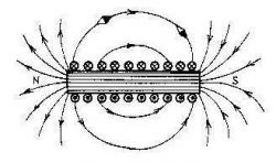
    This is the answer to yours directivity of the electromagnetic field . The magnetic field exits the coil
    http://moby.piwko.pl/pliki/sawicki1.htm
    120W induction heater - a typical gadget or a useful workshop tool?
  • ADVERTISEMENT
  • #36 17253731
    _lazor_
    Moderator of Designing
    robokop wrote:
    TechEkspert wrote:
    @_lazor_ if you have a ready construction, be sure to present it in DIY. This 100kV power supply had some huge resistive divider in the feedback loop or some kind of black magic?
    Such power supplies are not unusual - they are commonly used for insulation testing (old electricians and power engineers remember "kenetrons"). The voltage was also regulated there - because connecting full voltage immediately triggered the short-circuit protection system.


    But for 10kW? :D And I will add that it was a power supply for an electron gun, so at this 100kV potential there was another power supply to generate voltage on the Wehnelt cylinder.

    As for the directionality, it was more about the fact that on one side there was a magnetic armature, so made that it did not melt and only one side of the coil caused heating.
  • #37 17253998
    robokop
    VIP Meritorious for electroda.pl
    _lazor_ wrote:
    But for 10kW? And I will add that it was a power supply for an electron gun, so at this 100kV potential there was another power supply to generate voltage on the Wehnelt cylinder.
    Power supply with a voltage of 100kV with a power of 10kW ??? Some invention to knock down planes?
  • #38 17254044
    _lazor_
    Moderator of Designing
    I don't know what it went to, and if I did, I probably wouldn't say it anyway. However, there are devices such as clystrons where such a power supply can work.
  • ADVERTISEMENT
  • #39 17254132
    robokop
    VIP Meritorious for electroda.pl
    There is no Venhell cylinder in the klystron. :)
  • #40 17254247
    TechEkspert
    Editor
    robokop wrote:
    This is the answer to yours directivity of the electromagnetic field . The magnetic field exits the coil
    http://moby.piwko.pl/pliki/sawicki1.htm
    120W induction heater - a typical gadget or a useful workshop tool?


    But the field comes out only on one side, thanks to a piece of jumper made of an undefined material, you can also see a lot of Kapton tape on the wires leading to the coil.

    In general, magnetic circuits are probably not my forte, just like advanced inductance details are rather a mystery to me,
    although about the basics of inductance I once managed to do material: Some applications of inductance :)

    Anyway, I think that making material about something, making a project, etc. is the best way to learn something new.
  • #41 17254397
    _lazor_
    Moderator of Designing
    robokop wrote:
    There is no Venhell cylinder in the klystron. :)


    There is an electron gun in the klystron, which has a Wenhet cylinder, it would not make sense if the beam could not be regulated.
  • #42 18671069
    kudlatyco2
    Level 1  
    Hello. A bit old topic, but I will add my observations. I bought this toy some time ago, straight from a Chinese on ebay. It is admittedly low power, but quite a nice and useful device. In my DIY workshop, she has helped me many times to even remove or attach metal axles in plastic wheels of car models. Of course, I also started experimenting with the converter, which ended up puncturing the mosfets and giving her a vacation in a drawer. Recently, I found this post and, like the author of the article, replaced the transistors. There were no dedicated (in my case, the casings of the pierced mosfets were not damaged and the inscriptions could be read) or those suggested by the author of the post. So I soldered BUZ 11 and the heater came back to life. The transistors are big as for this design, but like the author, I have the impression that the converter works better than with the original ones: the PCB does not heat up, the induction heats up the elements faster. The article helped me a lot. I greet the author.

Topic summary

The discussion revolves around the utility of a 120W induction heater, particularly its effectiveness in workshop applications such as unscrewing stuck screws and hardening small metals. Users express skepticism about the heater's low power, noting that while it can achieve high temperatures, it may not be suitable for larger tasks or metals like steel. Some participants suggest alternatives with higher power ratings, while others share experiences of modifying the device for better performance. The conversation also touches on the importance of the heating method, the materials being heated, and the potential for radio interference. Overall, the consensus leans towards the device being more of a novelty than a practical workshop tool, although it can be useful for specific small-scale applications.
Summary generated by the language model.
ADVERTISEMENT