logo elektroda
logo elektroda
X
logo elektroda

How to avoid a short circuit when connecting the PK-1P relay to the gate?

rozx 1200 17
ADVERTISEMENT
Treść została przetłumaczona polish » english Zobacz oryginalną wersję tematu
  • #1 18080660
    rozx
    Level 10  
    How to avoid a short circuit when connecting the PK-1P relay to the gate?
    Hello,

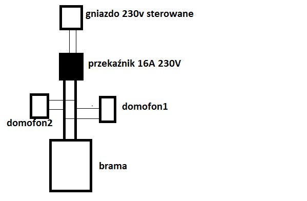
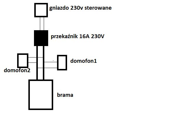
    I have connected a 230v socket (which I control from another device ) to a relay, the relay to the gate, in order to control it (by closing the circuit)
    Attached is a diagram of how I connected this.
    The relay is ELECTROMAGNETIC RELAY 16A 230V F&F PK-1P
    The way it works is that the socket gives voltage to the relay for a fraction of a second, the relay closes the circuit.

    After connecting everything worked fine, I made about 10 attempts, the gate opened and closed.
    After a couple of hours, I switched the socket on again (applied voltage) and the door started to open for about 1-2 seconds, and then the plugs blew - but not from the socket, but from the power supply to which the intercoms are connected.
    I dismantled the installation and fortunately nothing was broken, but I'm already afraid to carry out further tests.

    I am asking more experienced people to help me with what I might have done wrong. I think I have wired this simple diagram correctly.
    The only "problem" I've noticed with the socket is that sometimes, due to an error, the socket gives voltage for more than a fraction of a second e.g. 1-5 seconds (the solution could be a timer relay) but this is probably not a problem as it sort of mimics a longer button press and nothing happens then.

    Or maybe the relay itself is weak and it transmitted 230v? Is this possible ?
    The relay is an ELECTROMAGNETIC RELAY 16A 230V F&F PK-1P
    Thank you for your help
    How to avoid a short circuit when connecting the PK-1P relay to the gate?
  • ADVERTISEMENT
  • #2 18081006
    Zutket
    Level 36  
    And could you draw a diagram of how you wired it, as it doesn't show much from this block diagram. I understand that you are applying voltages to the coil of the relay, and that this contact short circuits the circuit in the control panel :?: and what is the control panel :?: .
  • #3 18086937
    Krzysztof Reszka
    Moderator of Electrical engineering
    rozx wrote:
    After connecting everything worked fine, I made about 10 attempts, the gate opened and closed.
    .
    What is this gate drive?
    And here is the reason probably for this failure. DTR.
    The contact load value indicated on the device refers to resistive loads (non-inductive loads for which the power factor parameter is 1 (cosφ=1)).
    Switching inductive or capacitive loads (e.g. motors, switching power supplies, etc.) leads to a significant reduction in contact life, e.g. a load for which cosφ=0.5 results in a reduction in life (number of switching cycles) of 20%, and for cosφ=0.25 even of 50%.
    .
  • #4 18087237
    Alpha
    Level 26  
    If I'm reading this schematic correctly, the relay contact operates virtually currentless, as it only controls the drive control panel input - so there can't be any contact burnout here (by the way, even if by some miracle it did burn out, it would either be a break or shorted permanently, but neither of the above would blow the plugs. Only a contact-coil puncture, but I doubt it). I understand that the two pads described as "intercom" are outputs to the solenoid lock.... The only thing I can think of is that these intercom outputs are not regular potential-free contacts, but feeding power to the bolt. Have you checked them?
  • #5 18087748
    rozx
    Level 10  
    In the diagram I drew, the connection to the intercom is also a 24v cable. On the intercoms I have a mechanical button which I use to close the circuit.
    I have also noticed that the gate opening indicator bulb has burned out after the fault....
    The gate motor is NICE.
    As far as the relay connection is concerned, I have connected 230v to contacts 1,3 and on the other side 11,12 cables (order doesn't matter I guess) which go to the gate.
    If any more info is needed let me know then I'll tell you. I still don't understand what could have caused the failure....
  • #6 18087771
    jack63
    Level 43  
    Where is the power supply to this 230VAC socket coming from?
    From the gate circuits?
    Schematic inaccurate.
  • ADVERTISEMENT
  • #7 18087779
    tos18
    Level 42  
    My impression is that the relay had nothing to do with it - simply a failure of the gate drive
  • ADVERTISEMENT
  • #8 18087802
    rozx
    Level 10  
    The power supply to the socket is from a different circuit to the gate.
    Gate failure - it would be suspiciously strange for it to happen just then. This has never happened
  • #9 18087812
    tos18
    Level 42  
    rozx wrote:
    the gate started to open for about 1-2 seconds, then the plugs blew - but not from the socket but from the power supply to which the intercoms are connected.
    .
    Are the gate and the intercoms on the same circuit ?
  • #10 18087818
    rozx
    Level 10  
    Yes, on the same one.
    To this one fuse is connected the gate drive, the power supply for the intercoms nothing else
  • #11 18088129
    Alpha
    Level 26  
    rozx wrote:
    In the diagram I drew, the connection to the intercom is also a 24v cable. On intercoms I have a mechanical button with which I close the circuit....
    .
    Well rather it is a mechanical contact, 24v cable.... - are you specifying its breakdown voltage here or what? ;) .
    I asked if the intercom puts voltage on this output to the deadbolt, or if it is potential free. Check it out!
  • #12 18088182
    rozx
    Level 10  
    I apologise if we do not understand each other
    It seems to me that this diagram may be misleading. What is labelled as an intercom in the drawing is actually an intercom but it only contains the button I use to open and close the gate.

    The other options of the intercom (voice, deadbolt for the gate, etc.) are routed via separate cables. So what is labelled as an intercom in the diagram could be seen as an independent, additional button to open /close the gate that has no connection to the intercom.

    I would also add that the voltage on the gate drive output is 24v, and closing this circuit opens/closes the gate

    And it still made me realise that the cause of the jams blowing out was not likely to be a voltage spike in the domfomn power supply, as I wrote earlier, but on the gate drive.... I still don't know why though
  • #13 18088232
    alster1
    CCTV and Stationary Alarms specialist
    rozx wrote:
    I have also noticed that after the failure, the signal bulb for opening the gate burnt out....
    I still don't understand what could have caused the failure...


    In my opinion this is the cause of the fuse tripping. Just a coincidence, a burned out bulb caused a short circuit.
  • #14 18088242
    tos18
    Level 42  
    alster1 wrote:
    Just a coincidence, a burned out bulb caused a short circuit.

    Is the bulb in the lamp on 230V ?
  • ADVERTISEMENT
  • #15 18088259
    rozx
    Level 10  
    This is the case at 230
  • #16 18088261
    alster1
    CCTV and Stationary Alarms specialist
    It depends on the lamp and the drive, I have a Faac on 230V. The bulbs often die from the vibration of the gate, it happened to me that a bulb just made a short circuit.
  • #17 18088284
    tos18
    Level 42  
    rozx wrote:
    Yes it is at 230
    .
    alster1 wrote:
    Bulbs often die from gate vibration, it happened to me that just a bulb made a short circuit.
    .
    And it's all clear.
  • #18 18088426
    rozx
    Level 10  
    Thank you for your advice,

    Of course it could have been the bulb (and that would be the best) but it seems strange to me that it's ok all year round and just on this day, an hour after the relay was installed it breaks down....
    Well... I guess there is no other idea for now....

Topic summary

The discussion revolves around the connection of a F&F PK-1P electromagnetic relay to control a gate via a 230V socket. The user experienced a failure where the gate opened briefly before the plugs blew, leading to concerns about potential short circuits. Responses highlight the importance of understanding the load type (inductive vs. resistive) connected to the relay, as inductive loads can significantly reduce contact life and cause failures. The user clarified that the intercom system is separate from the gate control, and the gate drive operates at 24V. The possibility of a burned-out bulb causing a short circuit was suggested, as well as the need to verify the nature of the intercom outputs. The conversation emphasizes the need for accurate wiring diagrams and understanding the electrical characteristics of connected devices to prevent future issues.
Summary generated by the language model.
ADVERTISEMENT