logo elektroda
logo elektroda
X
logo elektroda
ADVERTISEMENT
Treść została przetłumaczona polish » english Zobacz oryginalną wersję tematu
  • #31 18118926
    398216 Usunięty
    Level 43  
    arturavs wrote:
    Note, however, that such luck works casual.
    If such welded cores were ONLY in microwaves, then you would be 100% right. Unfortunately; many audio amplifiers also have a welded core. It is only about the fact that the production of such a transformer takes much less time - just put the "E" package on the other "I" and weld what would not fall apart. And that by the way such a way heats up more? In this case, it is secondary - the lower cost overcomes common sense.
    Renegat_pol wrote:
    Reality of the 1980s
    Box. Again, the cost of production is at stake. To this day I have two automatic transformers (flipper) wound without using a wireframe (Made in the early 70's in the USA). Not only that - not even flooded with any resin or other binder. Simply put the coils separately on the machine - and the wire will be tensioned as appropriate (and secured after winding so that it does not unwind like a released spring) faster and cheaper. And no winding protection (sealant or other shellac)? Nobody cared about it - it was faster and cheaper without.
  • ADVERTISEMENT
  • #32 18118932
    ArturAVS
    Moderator
    398216 Usunięty wrote:
    If such welded cores were ONLY in microwaves, then you would be 100% right. Unfortunately; many audio amplifiers also have a welded core. It is only about the fact that the production of such a transformer takes much less time - just put the "E" package on the other "I" and weld what would not fall apart. And that, by the way, this is more likely to happen
    heats? In this case, it is secondary - the lower cost overcomes common sense.

    That's right, however MOTs are definitely not for continuous operation and have a very high no-load current. In amplifiers this current is definitely smaller.
  • ADVERTISEMENT
  • #33 18118961
    398216 Usunięty
    Level 43  
    arturavs wrote:
    That's right, however .........

    That is why I wrote about luck in audio to show that the assumption that the welded cores were used only in microwaves due to the fact that he works in an intermittent work regime and that he would not buzz is not 100% true.

    PS Transformers with flippers have 600VA each.
  • #34 18118996
    ArturAVS
    Moderator
    398216 Usunięty wrote:
    Transformers made of flippers are 600VA each.

    Somewhere I am overturned somewhere safety 220/380 / 24V 6.3kVA from the 70s (due to the construction sometimes used as a welder :-) ), where there is no carcass.
    Windings wound with a solid copper flat bar (both), and tied with tape (I suspect cotton). In order to stiffen the windings, resotex wedges are hammered on the core.
    The whole strongly impregnated with electro-insulating varnish.
  • #35 18119009
    398216 Usunięty
    Level 43  
    arturavs wrote:
    Windings wound with a solid copper flat bar (both), and tied with tape (I suspect cotton). In order to stiffen the windings, resotex wedges are hammered on the core.
    The whole strongly impregnated with electro-insulating varnish.
    At least a copper flat bar with a large cross-section, tying the windings with tape and wedges ... These are not even mine. 2.5mm diameter wire on only one winding (there are several different voltages and currents) and inserted under the box, which is on the top of the windings, a plate made of thicker box with connectors for soldering the windings and output wires. As you look from above, you can see the individual layers of windings and insulation. NOT COVERED ANYTHING.
  • #36 18312007
    _lazor_
    Moderator of Designing
    How to design a pulse transformer

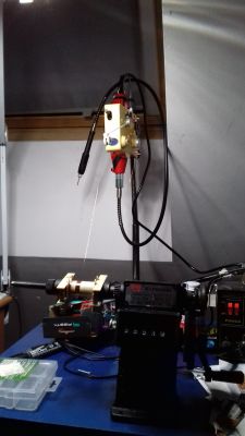
    Winding by hand is something extremely unpleasant, especially when you plan to wind more than a thousand turns of wire 0.1mm ... That's why I decided to make a mini winding station with a tensioner :D

    Next year there will be some topics with practical high voltage transformers, but based on the above calculations. We will see to what extent the practice and theory will agree ;)
  • ADVERTISEMENT
  • #37 18312813
    398216 Usunięty
    Level 43  
    _lazor_ wrote:
    I decided to make a mini winding position with a tensioner
    Beautiful. The only thing missing is automatic wire guidance with feed control :) This is not necessary in amateur use.
  • #38 18396474
    _lazor_
    Moderator of Designing
    I used the above calculations to design a high voltage transformer:

    How to design a pulse transformer

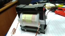
    Using the driver written on stm32f334 I was able to fire it in series resonance using the nightmare of high voltage transformers - capacity between turns of the secondary winding.
    It works as a current source, i.e. when there is no load it works in short circuit.


  • ADVERTISEMENT
  • #39 18396712
    Janusz_kk
    Level 39  
    Then maybe you will write something more about this converter because the topic is interesting.
  • #40 18396828
    _lazor_
    Moderator of Designing
    I'm going to make a really extensive article about this construction, but that's how I can describe it for a short time.

    Once I bought the book "Resonance circuits in power electronics" Tadeusz Citko, Henryk Tunia, Bolesław Winiarski. A very theoretical book, but that was what I needed - simplified mathematical models.
    There is a description of the construction "Serial inverters with a receiver connected in parallel to the capacitor", which construction in the world is called LCC and is a current source.

    Powered from 30V, but as it is a half bridge, 15V goes to the resonance circuit itself, the transformer ratio is 14: 850, which does not give much voltage with such a transmission. Due to the fact that the system works in resonance, reactive energy accumulates in the capacitor, which causes a voltage increase on this capacitor, and I decided that the capacitor will be ... the secondary winding. This works very well, although it will not be a cosmic efficiency construction, but you can get rid of the capacity problem on the secondary side to some extent.

    In a simple model it works like this:
    http://tinyurl.com/wq2s7d2
  • #41 19106190
    chlebok
    Level 10  
    How to choose the cross-section of the wires? Are there any formulas for this?
  • #42 19106206
    żarówka rtęciowa
    Level 37  
    Hello

    The conductor cross-section depends on the current density, which depends on the operating temperature, cooling conditions, etc.
  • #43 19106231
    _lazor_
    Moderator of Designing
    You have to calculate the resistance of such a wire, assume what effective current will flow through this winding and calculate the power losses. And now the most difficult thing is to count the thermal conductivity of the insulation (wire insulation and tapes insulation together). This already requires knowledge of materials and can be problematic ... You can also assume a fairly low current density, 2-3A / mm ^ 2 and hope a little that it will be a good value.
  • #44 19275104
    chlebok
    Level 10  
    @_lazor_ And in a converter with a power of several to several watts, do not you think that it can be assumed that 3 A / mm2 will be sufficient? On the featured many times on this forum page 2-3 A / mm2 is recommended, and 1-5A / mm2 in general.
  • #45 19275217
    _lazor_
    Moderator of Designing
    @ mechatron97 On the web you can find a lot of materials that show you how to calculate the thermal resistance and use it to calculate the wire thickness, but as we wrote earlier, it is not trivial and requires some knowledge of thermodynamics. Sample material:
    https://www.ti.com/lit/ml/slup126/slup126.pdf

Topic summary

The discussion revolves around the design and optimization of pulse transformers, particularly focusing on the impact of core materials and construction methods. Participants share insights on the use of welded cores in transformers, especially in microwave applications, and the trade-offs between production costs and efficiency. The conversation highlights the importance of calculating turns, wire gauge, and the effects of core saturation and eddy currents. Various transformer types, including network transformers and switching power supplies, are compared, emphasizing the need for different design considerations based on operational requirements. The role of magnetic fields in materials and the significance of core gaps are also discussed, along with practical experiences in transformer construction and design.
Summary generated by the language model.
ADVERTISEMENT