logo elektroda
logo elektroda
X
logo elektroda

ESP32 SPI with AS5048A Encoder: Troubleshooting Connection and Code Issues

madiz08 1875 21
ADVERTISEMENT
Treść została przetłumaczona polish » english Zobacz oryginalną wersję tematu
  • #1 18389149
    madiz08
    Level 14  
    I recently bought some AS5048A encoders, communicating with the master over SPI. I assembled a connection like this:
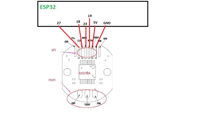
    ESP32 SPI with AS5048A Encoder: Troubleshooting Connection and Code Issues .

    and uploaded the example I found:
    Code: C / C++
    Log in, to see the code
    .

    Unfortunately after uploading the code to the ESP32 dev Module, I get the same zeros whether I apply the magnet or not. When I get home with this the first thing I'll check is that I have an SCL signal on the oscilloscope and that I have a low state on pin 27 every second, but I'd also like to ask if maybe something is wrong with the code or pinology?
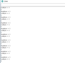
    ESP32 SPI with AS5048A Encoder: Troubleshooting Connection and Code Issues .
  • ADVERTISEMENT
  • #3 18389552
    madiz08
    Level 14  
    I also tried from HSPI pins before and there was no difference either. At the moment I have shortened the code from the link just to handle HSPI.
    Code: C / C++
    Log in, to see the code
    .
    However, I don't really understand how it works.
    When I was using I2C I knew that first you have to establish a connection, give the address, register address, how many bytes etc....
    With SPI I know that when picking up data from the slave, the CS pin is supposed to be in the low state, SCL is the clock, and MoSI and MISO are something like RX TX.

    In the loop I have a call to the communication function:
    Code: C / C++
    Log in, to see the code
    .
    Could you please explain what is contained in beginTransaction, and what is behind the transfer(stuff) command;

    https://www.mouser.com/datasheet/2/588/AS5048_DS000298_3-00-522570.pdf

    Added after 11 [minutes]:

    I'm looking for information on how to receive two bytes of encoder position information

    Added after 16 [minutes]:


    ESP32 SPI with AS5048A Encoder: Troubleshooting Connection and Code Issues .
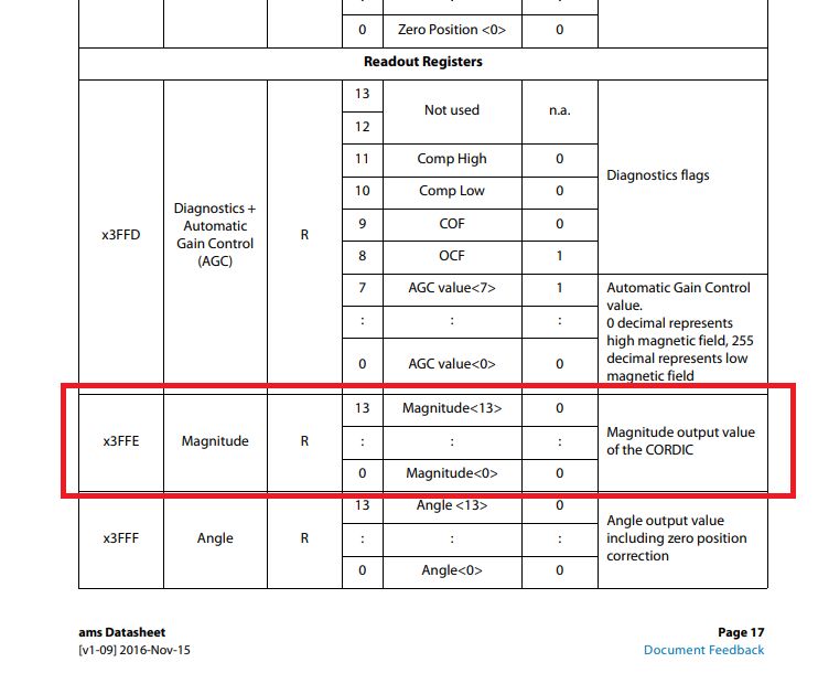
    Above I have the position read address, but how do I use this in code to read the contents of the register at address 0x3FFE?
  • Helpful post
    #4 18390155
    khoam
    Level 42  
    madiz08 wrote:
    what contains beginTransaction

    beginTransaction(SPISettings settings);
    SPISettings:
    uint32_t clock (default 1000000)
    uint8_t bitOrder (default SPI_MSBFIRST)
    uint8_t dataMode (default SPI_MODE0)
    This function sets up an SPI_MUTEX_LOCK on a given thread, which is later released by endTransaction().

    madiz08 wrote:
    what is behind the transfer(stuff) command;
    .
    void transfer(uint8_t * buffer, uint32_t size) - received data goes to the same buffer (instead of sent data); buffer size should be large enough
    uint8_t transfer(uint8_t data) - concerns only sending and receiving one byte
    https://www.arduino.cc/en/Reference/SPITransfer

    The whole SPI handling is quite well described at this link (also applies to ESP32):
    https://www.arduino.cc/en/Reference/SPI

    madiz08 wrote:
    Above I have the position read address, but how to use this in code to read the contents of the register at address 0x3FFE?
    .
    In a nutshell: send the appropriate command (in the transfer() buffer) and receive the response (also in the transfer() buffer).

    ESP32 SPI with AS5048A Encoder: Troubleshooting Connection and Code Issues .
  • #5 18409524
    madiz08
    Level 14  
    I was about to give up on it. I tried it on UNO and MEGA and got zero readings. Finally, using the link:
    https://forum.arduino.cc/index.php?topic=155238.0
    I noticed that MOSI is permanently connected to 3V3 and suddenly everything started to work. Below I am uploading the ready-to-read AS5048A on ESP32
    Code: C / C++
    Log in, to see the code
    .
    Thanks for the links to the SPI, a lot of news it gave me
  • Helpful post
    #6 18409773
    khoam
    Level 42  
    If the MOSI is permanently connected to HIGH, this means "Read only" mode for the AS5048A. - in the documentation you linked to in post #3 this is described on page 13. However, this does not mean that this is the way it has to be. You might want to program the encoder and change its settings? ;) .

    I would suggest moving the Serial.println(result) display behind the hspi->endTransaction() command. You should not block access to the SPI channel to other threads for longer than necessary.
  • ADVERTISEMENT
  • #7 18410863
    madiz08
    Level 14  
    Of course I would like to be able to program it, or a more apt word is to be able to. I would be most interested in setting the zero position. I understand the Transfer function as sending the appropriate byte, and in response the function returns a response in place of that byte.
    I don't understand why this response comes after sending two bytes with a value of 0? I know the value is 14-bit, so we are not looking at the two oldest bits, but why are we sending 0?
    Is it not really a 0, just the first byte of the array?
    The register address I'd like to read the position from is 0x3FFE. I thought it would work on the principle that I split this value into two bytes, add a 1 to the older one in the 15th bit to let it know it's a read, and send that to the encoder. I've also tried Transfer(Val16), but also nothing.
  • #9 18412478
    madiz08
    Level 14  
    I now understand everything. Tracing
    Code: C / C++
    Log in, to see the code
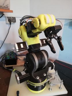
    made everything clear to me. That is, we send the appropriate command + a 1 in front and then send 0 as a read. I had sent the former before, but didn't know that you then have to send a 0 to get the response. I'm ordering 6-wire shielded cables and when they arrive I'll try to fit these encoders to my robot instead of the AS5600. I hope that if they are connected directly to the ESP32 there will be no interference.
    Thank you.
  • #10 18413850
    khoam
    Level 42  
    madiz08 wrote:
    I hope that if they are connected directly to the ESP32, there will be no interference.
    .
    What length will this 6 wire cable be?
  • ADVERTISEMENT
  • #11 18415794
    madiz08
    Level 14  
    the one from the furthest axle 180cm
  • #12 18429302
    madiz08
    Level 14  
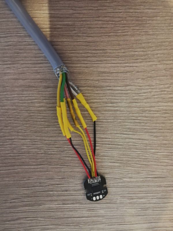
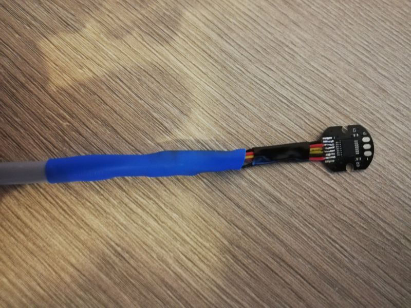
    Today I soldered the encoders to the shielded cable
    ESP32 SPI with AS5048A Encoder: Troubleshooting Connection and Code Issues .

    ESP32 SPI with AS5048A Encoder: Troubleshooting Connection and Code Issues .
    and I temporarily connected 2 of the 5 encoders on a test basis in a "3 Wire Mode (read only)" connection.
    ESP32 SPI with AS5048A Encoder: Troubleshooting Connection and Code Issues .
    Tomorrow or the day after tomorrow (if I don't have trips at work), I will try to assemble the encoders on the individual axes and see how it works.
    I'm just asking for input on whether this kind of reading is optimal?
    Code: C / C++
    Log in, to see the code
    .

    Code: C / C++
    Log in, to see the code
    .
  • #13 18429426
    khoam
    Level 42  
    madiz08 wrote:
    I am just asking for information if such a reading is optimal?
    .
    An object of class SPSettings can only be created once and then used in a loop:
    Code: C / C++
    Log in, to see the code
    Code: C / C++
    Log in, to see the code
    .
  • ADVERTISEMENT
  • #14 18442128
    madiz08
    Level 14  
    Today I quietly connected everything, separated the 5V control voltage from the motors supply voltage. After switching on the control and moving the axes freely, 0 reading errors, but unfortunately after switching on the power supply to the motors automatically erroneous readings.
    Well, I don't know where the interference comes from anymore. The same encoders are used in professional applications by Boston Dynamisc who use them in their motors doing such wonders:
    https://www.youtube.com/watch?v=NR32ULxbjYc
    Perhaps my problem is that the encoders and magnets are not in a metal box forming a Faraday shield and the magnetic field of the motors affects their reading, or perhaps the ESP32 itself is too susceptible to interference.
    Overall communication with AS048A resolved, but it's a shame not with positive results :) .
  • #15 18442596
    khoam
    Level 42  
    madiz08 wrote:
    After switching on the control and freely moving the axes 0 reading errors, but unfortunately after powering up the motors with the automatic erroneous readings.
    .
    Can you approach on an oscilloscope what these disturbances on the SPI bus look like when the motors are switched on?

    madiz08 wrote:
    and perhaps the ESP32 itself is too susceptible to interference
    .
    If this is a standard module from the ESP32 then it was not designed to withstand this kind of interference How close is this module to the motor? In the first instance I would screen the electronics module from the ESP32 and use an external WiFi antenna for the ESP32.

    Maybe post a picture of what this whole circuit looks like?
  • #16 18442881
    madiz08
    Level 14  
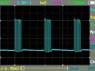
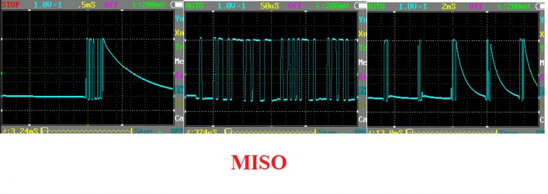
    Well, an oscilloscope indeed! Unfortunately it is of the lower regiment, but it shows something:

    ESP32 SPI with AS5048A Encoder: Troubleshooting Connection and Code Issues .
    Above, the MISO signal at intervals with the engines switched off

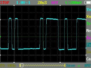
    ESP32 SPI with AS5048A Encoder: Troubleshooting Connection and Code Issues
    and here approximately. Unfortunately my oscilloscope does not give a full view of the whole frame
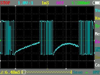
    Below please see what the signal looks like when the power supply is switched on:
    ESP32 SPI with AS5048A Encoder: Troubleshooting Connection and Code Issues .
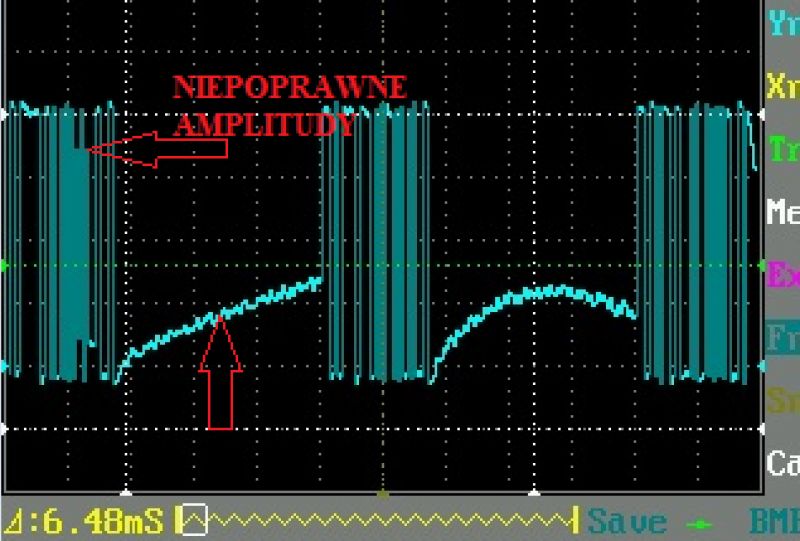
    and approximately:
    ESP32 SPI with AS5048A Encoder: Troubleshooting Connection and Code Issues .
    I am also sending a short video where it is shown what it looks like before and after the engines are switched on.


    https://www.youtube.com/watch?v=qlD52KkkEK8&feature=youtu.be if the video does not fire
    I have in the program that if the reading is 300 position units higher or lower than the previous reading, it is supposed to fire an error with an alarm. Sreial.print here has no effect on anything. I tried controlling the robot without serial and also position errors unfortunately.
    I'm having a temporary problem flipping pictures from my phone, but on the picture with the previous I2C multiplexer it looked similar:
    ESP32 SPI with AS5048A Encoder: Troubleshooting Connection and Code Issues .
    ESP32 SPI with AS5048A Encoder: Troubleshooting Connection and Code Issues .
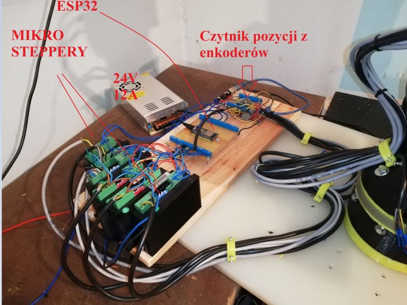
    Now there is a board where the shielded encoder wires are plugged in and connecting all of them:
    +Vcc
    GND to which the shield is connected
    MISO
    SCK
    these 4 above wires at the output of the board go about 10cm by wires to the ESP32. Each CS wire also goes loosely to the ESP32. I won't be able to do any more today as I'm leaving the house, but tomorrow I'd like to try hooking up the encoder board to an Arduino Mega with a read only program uploaded and see if it's the same. Thanks for the hint with checking the signal on the oscilloscope
  • #17 18443036
    khoam
    Level 42  
    madiz08 wrote:
    Now there is a board where the shielded encoder wires are plugged in and connecting all:
    .
    Please write exactly how you connected the shield from these wires. On both sides of the wires?
  • Helpful post
    #18 18443203
    Slawek K.
    Level 35  
    The motor cables should also be shielded, a subject well known from 3D printers, for example, where the proximity of motor cables and e.g. tap wires caused the stop to be switched on due to the interference generated.


    Regards
  • #19 18443422
    madiz08
    Level 14  
    ESP32 SPI with AS5048A Encoder: Troubleshooting Connection and Code Issues .
    This is how it looks when it comes to the encoder wires
    Regarding the motor cables, I somewhat regret that I did not use shielded cables right away. If it would have helped then I will definitely replace them with shielded ones.
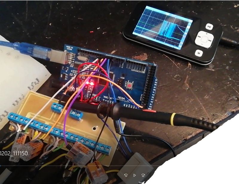
    I'm about to get round to switching everything over to reading the position from the Arduino Mega, just out of curiosity as to whether changing the microcontroller here will have any effect on the correctness of the reading.
  • #20 18443628
    khoam
    Level 42  
    In longer cables with measurement signals, in this case the SPI bus, the shield should only be connected to ground on one side, in this case the ESP32 side.
    In cables where more current flows, the shield should be connected to ground on both sides.
  • #21 18443662
    madiz08
    Level 14  
    ESP32 SPI with AS5048A Encoder: Troubleshooting Connection and Code Issues .
    I quickly assembled something like the one above and it's the same, admittedly now only misreading from one encoder (I'll ditch it later), but there it is.

    ESP32 SPI with AS5048A Encoder: Troubleshooting Connection and Code Issues .
    ESP32 SPI with AS5048A Encoder: Troubleshooting Connection and Code Issues

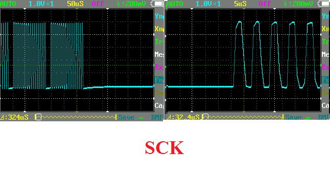
    SCK signal seems ok, CS signals are 100% perfect. Regarding the MISO, I wonder why the signal doesn't drop instantly to zero after readings, but often goes down slowly to ground potential.
    I have the MOSI pin on the Arduino side unconnected

    Added after 2 [minutes]: .

    I see, I will also try disconnecting the screen from the encoder side

    Added after 4 [hours] 32 [minutes]:

    Hmmm... All I did was isolate the screen from ground at each encoder according to the guidelines and to my surprise (as I've always been told the screen should be wherever it goes) complete lack of erroneous readings. I typed in the code to count the erroneous readings and display the status of this counter every second and for over an hour the counter status was 0, also great, thank you for such a guideline. For now I have this result for the Arduino Mega, tomorrow I'll try to get the wires in order in conjunction with the ESP32 and hopefully eventually get the robot "driving" :) .
    But I'm puzzled as to why isolating the ground from the shield at the encoder resulted in better interference cancellation?
  • #22 18445327
    khoam
    Level 42  
    madiz08 wrote:
    But it puzzles me why isolating the ground from the shield at the encoder resulted in better interference cancellation?
    .
    In a nutshell: interference from the encoder to the Mega stopped flowing through the shield :)
    A cable screen connected to ground on two sides is a bit like a receiving antenna for interference. The longer, the better the antenna.

Topic summary

The discussion revolves around troubleshooting issues with the AS5048A encoder connected to an ESP32 via SPI. The user initially faced problems with the encoder not providing readings, despite following example code and wiring diagrams. Key points included the need to ensure correct SPI bus configuration (VSPI vs. HSPI), proper handling of the MOSI pin, and the importance of sending a zero byte after the command to receive data. The user discovered that interference from motors affected readings, leading to erroneous outputs. Solutions discussed included using shielded cables, isolating the ground connection of the shield, and ensuring proper SPI transaction handling. Ultimately, the user achieved successful communication with the encoder after addressing these issues.
Summary generated by the language model.
ADVERTISEMENT