FAQ
TL;DR: ESP32-to-ESC no-response is usually wiring, not code; "According to the documentation it is supposed to be 1 kHz." Share ground and verify PWM to resolve it fast. [Elektroda, khoam, post #18710653]
Why it matters: For makers wiring an ESP32 to a Graupner Speed Profi 40R BEC brushed ESC, this fixes the common "no response" problem.
Quick Facts
- A common ground between ESP32 and the ESC battery is mandatory, or the ESC may ignore the signal. [Elektroda, lukaszd82, post #18710613]
- ESP32 GPIO input tolerates up to 3.6 V; a 3.5 V signal on the ESC lead is safe. [Elektroda, khoam, post #18710626]
- Reported control frequency for this Graupner unit: 1 kHz PWM; confirm with your specimen. [Elektroda, khoam, post #18710653]
- Example MicroPython used 50 Hz PWM and duty sweep 0–1020 steps during testing. [Elektroda, prem111, post #18710526]
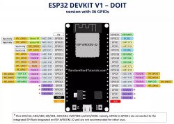
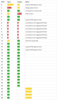
- GPIO2 often drives an onboard LED on ESP32 dev boards; avoid it for ESC signaling. [Elektroda, lukaszd82, post #18710505]
How do I fix my ESP32 not controlling the Graupner Speed Profi 40R BEC ESC?
First, connect the ESC battery ground to the ESP32 ground. Then verify your PWM output and frequency. Quick How-To: 1. Tie grounds (ESC GND to ESP32 GND). 2. Test PWM with a servo or LED. 3. Reconnect the ESC to a clean GPIO and retry. The original poster confirmed success after sharing ground. [Elektroda, prem111, post #18710694]
Do I need a common ground between the ESP32 and the ESC battery?
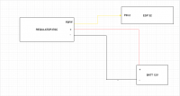
Yes. Without a shared ground, the ESC cannot reference the signal, so it won’t respond. "The regulator and ESP generating the PWM signal should share a common ground." Tie grounds carefully and double-check polarity. [Elektroda, lukaszd82, post #18710613]
What PWM frequency should I start with for the Graupner Speed Profi 40R BEC?
Start at 1 kHz if your unit matches the cited documentation. One member noted, "According to the documentation it is supposed to be 1 kHz." If unsure, try 1 kHz, then test servo-style 50 Hz if needed. [Elektroda, khoam, post #18710653]
Can I use GPIO2 for the ESC signal on ESP32?
Prefer a different pin. On many boards, GPIO2 drives an onboard LED, which can distort PWM or interfere at boot. Use a free PWM-capable pin instead, and reserve GPIO2 for the LED if present. [Elektroda, lukaszd82, post #18710505]
How should I wire the ESC’s three-wire lead to the ESP32?
Connect the ESC signal wire to a PWM-capable GPIO. Connect the ESC ground to ESP32 GND. Leave the positive BEC lead disconnected unless powering accessories. "Just don't mix up the poles or there will be smoke." Verify polarity before powering. [Elektroda, lukaszd82, post #18710613]
Is 3.5 V logic on the ESC signal safe for an ESP32 GPIO?
Yes. ESP32 inputs are safe up to 3.6 V. As one member put it, "Up to 3.6v is still safe for the ESP32." That makes a 3.5 V servo-type signal acceptable. [Elektroda, khoam, post #18710626]
My servo moves, but the ESC stays silent—what should I check?
Check for a common ground first. Many no-response cases resolve once grounds are tied. Then confirm your PWM frequency and any arming behavior. The reported fix came from sharing ground between the battery and ESP32. [Elektroda, prem111, post #18710694]
How can I test my PWM output without an oscilloscope?
Use an LED with a suitable resistor on the signal pin. Change duty cycle and watch brightness vary. This confirms PWM is present. You can also swap in a known-good servo to validate timing quickly. [Elektroda, lukaszd82, post #18710550]
Do I need a scope to diagnose this?
A scope helps confirm amplitude, frequency, and duty cycle. At minimum, verify the waveform at the ESP32 pin before suspecting the ESC. The thread explicitly asked about checking the output with an oscilloscope. [Elektroda, jrk13, post #18710424]
Why did it work on Raspberry Pi but not on ESP32?
When powering the ESC from a separate battery, the ESP32 may lack a common ground. The Pi setup may have shared ground through its supply. Tie the grounds between ESC and ESP32, then retest. [Elektroda, lukaszd82, post #18710613]
What MicroPython settings were used in the thread example?
The example used machine.PWM at 50 Hz on GPIO2 and swept duty from 0 to 1020. Typical MicroPython duty uses approx. 0–1023 steps, so that sweep covers the range. Re-test after fixing wiring. [Elektroda, prem111, post #18710526]
Is it safe to power the ESP32 from the ESC’s BEC output?
Avoid connecting the ESC’s BEC to ESP32 Vcc without documentation. "Without documentation it's always a risk that you'll burn something." Confirm voltage and current before tying supplies together. [Elektroda, lukaszd82, post #18710632]
What if I can’t find documentation for this Graupner ESC?
Proceed carefully and confirm the three-pin mapping before wiring. A contributor noted documentation was hard to find and requested a 3‑pin description. Lack of docs increases risk of wiring mistakes. [Elektroda, lukaszd82, post #18710632]
Any critical gotchas before powering up?
Yes. Ensure a shared ground and correct polarity; reversing leads can cause damage. Double-check the signal pin choice and boot behavior. Keep an eye on GPIO2 if an onboard LED is present. [Elektroda, lukaszd82, post #18710505]


