logo elektroda
logo elektroda
X
logo elektroda

Exploring SP530E 5CH PWM+SPI LED Controller with OpenESP on ESP32-C3

divadiow 5826 36
ADVERTISEMENT
  • #1 21230102
    divadiow
    Level 35  
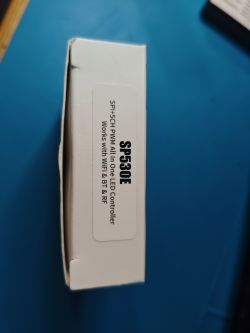
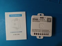
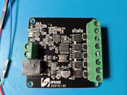
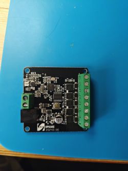
    Hi. So this is an SP530E 5CH PWM+SPI LED controller sold by BTF Lighting, and other generics, as model SP530E. I was going to play with WLED on it at some point, but now OpenESP is in development, that can be tested on it as well.
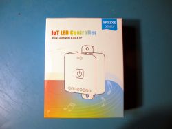
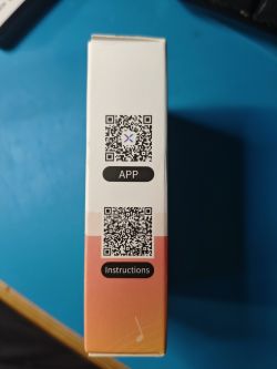
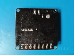
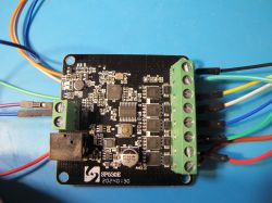
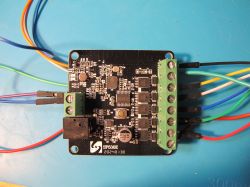
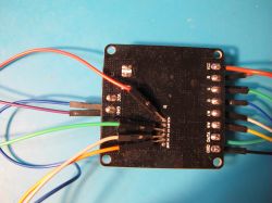
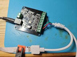
    Box of the SP530E series IoT LED controller. Side of a box with two QR codes labeled APP and Instructions. Box of SP530E LED controller with compatibility information. SP530E LED controller and user manual on a blue background. Bottom view of the SP530E LED controller board with visible pads and pin labels. SP530E LED controller with visible components on a printed circuit board. View of LED controller SP530E 5CH PWM+SPI on a blue background. LED controller SP530E with connected wires SP530E LED controller on a blue background with connected wires. SP530E LED controller with connected wires, top view
    The app QR is for the same BanlanX app seen in https://www.elektroda.com/rtvforum/topic4064640.html#21151364
    The device uses an ESP32-C3.

    With the pads on the back soldered up and IO9 pulled low esptool.exe commands can be run for some chip info:

    esptool.exe --port COM22 flash_id
    Code: Text
    Log in, to see the code


    esptool.exe --port COM22 get_security_info
    Code: Text
    Log in, to see the code


    After a bit of reading I turned off the security features with
    Code: Text
    Log in, to see the code


    So the security info is now
    Code: Text
    Log in, to see the code

    And I'm free to flash unencrypted binaries and they'll boot.

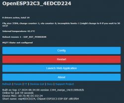
    Which means a bootable OpenESP32C3
    Code: Text
    Log in, to see the code


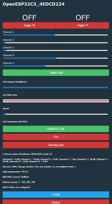
    Screenshot of OpenESP32C3 interface for ESP32-C3 device

    Most of what I've understood about this device is from the WLED Discord and mostly thanks to user triangulumsweetrolls.

    Code: Text
    Log in, to see the code


    Code: Text
    Log in, to see the code


    Code: Text
    Log in, to see the code


    That last comment about pin 19 is because pins 12-19 are not usable on WLED. You need to build a custom firmware to disable USB_CDC. See https://github.com/zalatnaicsongor/wled-compiler

    and regarding the user's custom WLED build:
    Code: Text
    Log in, to see the code


    Back to OpenESP. I've got the basic PCB LEDs on IO0/1 working of course, but no PWM led, at any frequency (assuming command 'pwm frequency xxxxx' is expected to work) and there's no OpenESP support yet for SPI.

    In the custom WLED binary I could only get dimly lit/barely working PWM LEDs but I did achieve working animations on 4m WS2812B strip using unlocked IO19.

    That's it really. It's not been the best device to test on.

    Added after 3 [minutes]:

    fac backup and partition table fwiw
  • ADVERTISEMENT
  • #2 21230139
    divadiow
    Level 35  
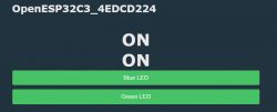
    Screenshot of a control panel interface with OpenESP32C3_4EDCD224 and buttons turned on for blue and green LEDs.

    Code: Text
    Log in, to see the code

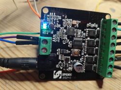
    Close-up of an electronic circuit board with visible components and a lit LED.
  • #3 21231354
    p.kaczmarek2
    Moderator Smart Home
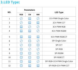
    That's interesting, I haven't seen yet 5 PWM + SPI LED device. I saw only either 5 PWM, or SPI RGB, or SPI RGB + 2 PWM CW. What is the purpose of 5 PWM + SPI LED device? How it works from app? Do they allow to control SPI LED strip and RGBCW strip independently?
    Helpful post? Buy me a coffee.
  • ADVERTISEMENT
  • #5 21231424
    divadiow
    Level 35  
    I don't think I see anything that says they can't be controlled independently.
  • ADVERTISEMENT
  • #6 21231433
    p.kaczmarek2
    Moderator Smart Home
    OBK PixelAnim currently assumes that LED RGB mode is the same as per-pixel mode with single color so we will need some kind of clever check in code to handle situation from this topic. Maybe conditional statement to check if the number of set PWM pins is equal to 5.
    Helpful post? Buy me a coffee.
  • ADVERTISEMENT
  • #7 21231545
    divadiow
    Level 35  
    I understand. OK. Something to consider when SPI is working I guess?
  • Helpful post
    #8 21231563
    p.kaczmarek2
    Moderator Smart Home
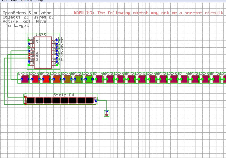
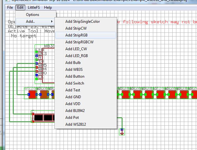
    Maybe I could try earlier in Simulator, depending on how big the demand is?
    Screenshot from OpenBeacon simulator showing a circuit on a grid.
    Screenshot of OpenDeck Simulator software showing a menu for adding electronic components.
    PS: I added a switch (bistable) and zoom features to Simulator yesterday.
    Helpful post? Buy me a coffee.
  • #9 21231567
    divadiow
    Level 35  
    p.kaczmarek2 wrote:
    depending on how big the demand is?

    I guess it's only me/this device so far and I don't have an immediate use in mind. It was unpackaged for ESP testing. Maybe new members will flock to the forums now ESP is in progress!

    Added after 7 [minutes]:

    re the reported 16khz factory PWM for this device specifically, is the command pwmfrequency ### expected to be effective on ESP at this stage?
  • Helpful post
    #10 21231588
    p.kaczmarek2
    Moderator Smart Home
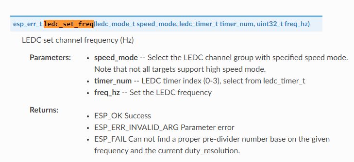
    It seems that LEDC is used for PWM:
    https://docs.espressif.com/projects/esp-idf/e...ble/esp32/api-reference/peripherals/ledc.html
    And there is a function for that:
    ledc_set_freq
    but I can't see it used here:
    https://github.com/openshwprojects/OpenBK7231...c888c1f11e6e/src/hal/espidf/hal_pins_espidf.c
    So probably @insmod still has to add it?

    Added after 49 [seconds]:


    Screenshot of ledc_set_freq function documentation with a list of parameters and return values.
    Helpful post? Buy me a coffee.
  • #11 21248382
    divadiow
    Level 35  
    No PWM joy with latest ESP build at any frequency tried.

    Perhaps interesting is this Discord comment regarding a custom build of WLED for this device

    Code: Text
    Log in, to see the code


    This device is a bit of an oddball I think. Just updating thread, rather than suggesting anything needs changing.

    Added after 49 [seconds]:

    is the bit level adjustable? does that even apply/make sense?
  • #12 21331970
    vo1xabrad
    Level 2  
    >>21230102 How do I reflash the original firmware? What are the esptool commands?

    Added after 24 [minutes]:

    >>21331970 I cannot get WLED to boot on my SP530E. Here's a copy of my terminal output:

    $ esptool.py -b 115200 write_flash 0x0 C3_bootloader.bin 0x8000 C3_partitions_4M.bin 0x10000 WLED_0.15.0-b7_ESP32C3_4MB.bin
    esptool.py v4.8.1
    Found 33 serial ports
    Serial port /dev/ttyUSB0
    Connecting...
    Detecting chip type... ESP32-C3
    Chip is ESP32-C3 (QFN32) (revision v0.4)
    Features: WiFi, BLE, Embedded Flash 4MB (XMC)
    Crystal is 40MHz
    MAC: f0:f5:bd:c4:c9:68
    Stub is already running. No upload is necessary.
    Configuring flash size...
    Flash will be erased from 0x00000000 to 0x00002fff...
    Flash will be erased from 0x00008000 to 0x00008fff...
    Flash will be erased from 0x00010000 to 0x00186fff...
    Compressed 12144 bytes to 8820...
    Wrote 12144 bytes (8820 compressed) at 0x00000000 in 1.0 seconds (effective 94.9 kbit/s)...
    Hash of data verified.
    Compressed 3072 bytes to 128...
    Wrote 3072 bytes (128 compressed) at 0x00008000 in 0.1 seconds (effective 307.2 kbit/s)...
    Hash of data verified.
    Compressed 1532080 bytes to 940926...
    Wrote 1532080 bytes (940926 compressed) at 0x00010000 in 83.8 seconds (effective 146.3 kbit/s)...
    Hash of data verified.

    Leaving...
    Hard resetting via RTS pin...
    $

    I've been at this for hours now to no avail. PLEASE HELP!
  • #13 21332044
    divadiow
    Level 35  
    what is the current security info output?

    esptool.exe --port COM## get_security_info

    im not sure going back to factory is an option if you've already run these two commands to turn off the security features

    Code: Text
    Log in, to see the code


    Added after 9 [minutes]:

    also. to use WLED your best best is to use this custom build

    https://discord.com/channels/473448917040758787/719873873071308821/1258319577222484031
    https://github.com/zalatnaicsongor/wled-compiler/tree/main

    search SP530E on the WLED Discord for history on this
    https://discord.gg/WNTsyzN2
  • #14 21332556
    vo1xabrad
    Level 2  
    >>21332044 How do I determine if I have flashed the WLED firmware successfully? Currently, the blue and green LEDs on board only flash briefly while I attach the power cable. Nothing more than that.
  • #15 21333651
    divadiow
    Level 35  
    I'd expect the WLED starter AP to broadcast.

    What do the boot logs look like from UART TX after flashing custom WLED and powering up?
  • Helpful post
    #16 21635132
    divadiow
    Level 35  
    went back to this now there's SPI LED support in OpenESP

    wiped an October 2024 PR and re-flashed with the 4MB OpenESP32C3_1.18.154_4M.factory.bin

    P19 set as SM16703P_DIN

    autoexec
    Code: Text
    Log in, to see the code


    100ohm on DAT line.

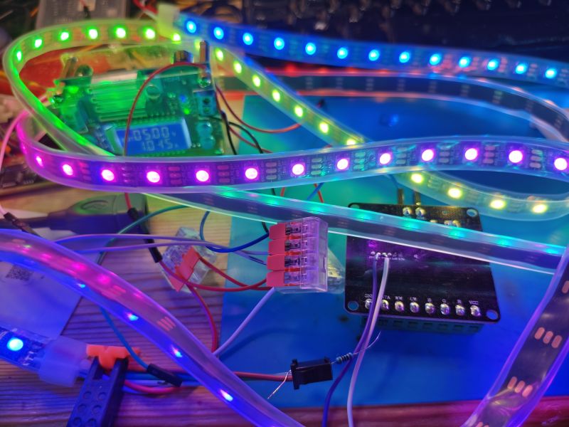
    Rainbow animation running happily on 5V 2M strip
    Colorful SPI LED strip connected to microcontroller with wires on a desk

    current basic template

    16/08 - updated
    Code: JSON
    Log in, to see the code


    Added after 18 [minutes]:

    ignoring weird PWM, I think working SPI is finally worthy of a device list add https://github.com/OpenBekenIOT/webapp/pull/213
  • #18 21635231
    divadiow
    Level 35  
    hmm. not even a glimmer on any channel. 16khz set in PR.

    12v dc in, 12v LED strip
    Electronic module with connected wires and 12V LED strip on blue mat

    Added after 2 [minutes]:

    going to try higher

    Added after 4 [minutes]:

    insmod wrote:
    There can be a problem with duty_resolution though...

    but yes

    Code: C / C++
    Log in, to see the code
  • #19 21635239
    insmod
    Level 27  
    >>21635231
    What shows up in log during pin setup?
    Btw, you can set freq to 2000, like in custom wled firmware.

    Added after 2 [minutes]:

    2000, not 20000
  • #20 21635243
    divadiow
    Level 35  
    insmod wrote:
    2000, not 20000

    yes. that was my higher attempt.

    2k build running

    Added after 5 [minutes]:

    i see

    Code: Text
    Log in, to see the code


    trying 2k

    Added after 5 [minutes]:

    divadiow wrote:
    trying 2k


    Code: Text
    Log in, to see the code


    still no love
  • #22 21635287
    divadiow
    Level 35  
    insmod wrote:
    Does it even work if set as relay?

    no LEDs light but I see channels jumping from ~12v to ~0v. 1 or two stay high and a couple are Rel_n it seems. bit weird. 7bit build running

    Added after 3 [minutes]:

    can't go back to factory even now that efuse was changed to disable security. might have 1 go left to switch back on I think.

    this is more about completing a template for any users that wish to convert than a working device for me
  • Helpful post
    #23 21635292
    insmod
    Level 27  
    Set 16khz next. duty_resolution have no impact here, only to allow higher frequencies.
  • #24 21635304
    divadiow
    Level 35  
    darn still nothing.

    Code: Text
    Log in, to see the code


    have switched all to pwm_n. yes im using web app to turn each main colour on/off as well as gui picker. not a peep.

    hope something isn't faulty. LED strip was tested OK with BK7231T controller/12v DC before.

    going to call it a night. thanks for suggestions to try stuff
  • #25 21636228
    divadiow
    Level 35  
    OK OK. So I'd not realised the switching is on ground, not VCC 😬 despite eyeballing the V+ pin alongside RGB channels on a different LED strip controller just before

    RGBCW each measure 5V.

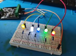
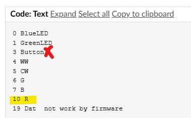
    With 1.27, 7BIT and 16khz GBCW all light up BUT red is odd. LED works, resistor works, cabling works but red channel is never seen. Maybe the 80N03 for this channel is dodgy (or the 74HC245D). I'll try other other builds maybe, but not sure why red would be different to the others. Because R is GPIO10 :)

    I guess this config would always mean a user custom build rather than being able to adjust these things in OBK GUI or CLI

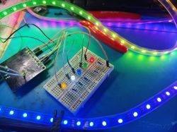
    Five lit LEDs in different colors mounted on a breadboard with connecting wires

    Added after 1 [hours] 24 [minutes]:

    divadiow wrote:
    Because R is GPIO10


    ffs. was stated here. button was wrong though

    GPIO assignment list with GPIO 10 as R highlighted and GPIO 3 marked with red X
  • #26 21636503
    insmod
    Level 27  
    What about release version?
    Do LEDs work at 1khz?
  • Helpful post
    #27 21637433
    divadiow
    Level 35  
    insmod wrote:
    Do LEDs work at 1khz?

    omg ffs. after all that fiddling, yes

    but why other frequencies reportedly required in WLED posts. hmm

    Added after 45 [minutes]:

    other things to note with this device because there is only 1 colour picker:

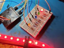
    -With SPI and PWM pins assigned, turning on the WS2812B with "Toggle Light" will make the WS2812B white and the RGB PWM LEDs light up.
    -Choosing animation will start animation and turn off PWM LEDs
    -choosing solid colour in picker will light WS2812B and PWM LED to matching colour

    Breadboard with colored LEDs and jumper wires, WS2812B LED strip glowing red

    -Flag 3 enabled ([LED][Debug] Show raw PWM controller on WWW index instead of new LED RGB/CW/etc picker) allows you to run animations and choose PWM colours separately


    WS2812B LED strip connected to breadboard with RGB LEDs and wiring

    LED control interface in OpenESP32C3 system with active animation
  • Helpful post
    #28 21640553
    p.kaczmarek2
    Moderator Smart Home
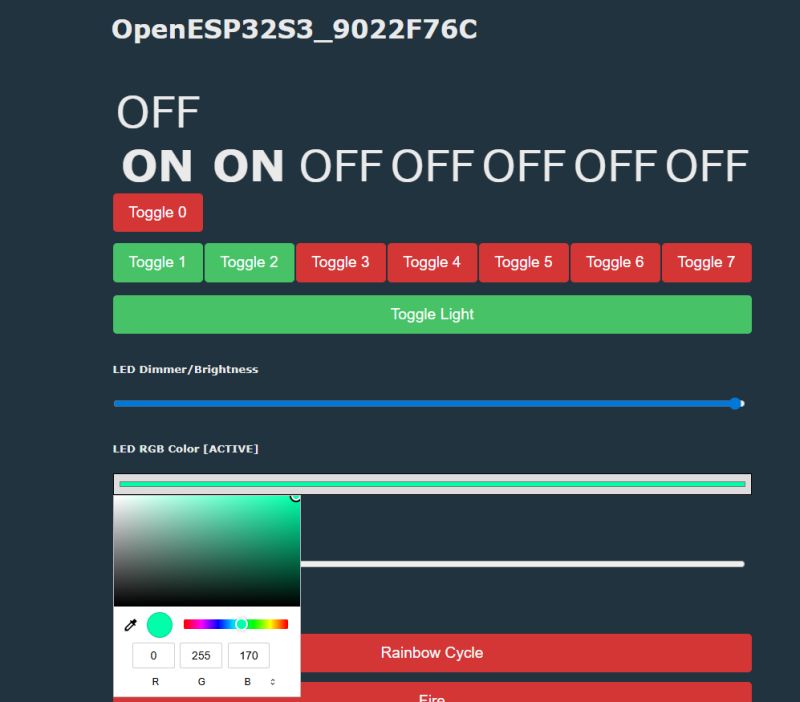
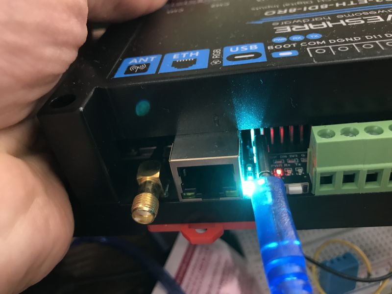
    ESP32-S3-ETH-8DI-8RO has single RGB WS2812 LED, let's try.

    Pin configuration for IO34–IO42 with SM16703P_DIN set on IO38
    
    startDriver TCA9554 41 42 0
    setChannelType 0 Toggle
    setChannelType 1 Toggle
    setChannelType 2 Toggle
    setChannelType 3 Toggle
    setChannelType 4 Toggle
    setChannelType 5 Toggle
    setChannelType 6 Toggle
    setChannelType 7 Toggle
    
    startDriver SM16703P
    SM16703P_Init 1GRB
    SM16703P_SetPixel 0 255 0 0
    SM16703P_Start
    startdriver pixelanim
    

    OpenESP32S3 web interface with toggle buttons and RGB LED color control
    Close-up of ESP32-S3-ETH-8DI-8RO ports with active blue LED and USB cable

    Added after 7 [minutes]:

    Works from HA

    Home Assistant control panel showing esp9022F76C with Light feature enabled

    Added after 47 [minutes]:

    @insmod I managed to crash ESP.

    Possible repo:
    1. setup WS2812 ESP32
    2. do clearConfig obk command (LFS will stay!)
    3. now it crashes on every safe boot with:
    
    
    fo:CMD:CMD_StartScript: started @startup at the beginning
                        
    
    fo:CMD:CMD_StartScript: started autoexec.bat at the beginning
                    
    
    fo:BERRY:[berry init]
                                                            
    
    fo:BERRY:[berry start]
                                                           
    
    fo:MAIN:Started TCA9554.
                                                         
    
    fo:GEN:Channel 0 type changed to Toggle
                                          
    
    fo:GEN:Channel 1 type changed to Toggle
                                          
    
    fo:GEN:Channel 2 type changed to Toggle
                                          
    
    fo:GEN:Channel 3 type changed to Toggle
                                          
    
    fo:GEN:Channel 4 type changed to Toggle
                                          
    
    fo:GEN:Channel 5 type changed to Toggle
                                          
    
    fo:GEN:Channel 6 type changed to Toggle
                                          
    
    fo:GEN:Channel 7 type changed to Toggle
                                          
    
    fo:MAIN:Started SM16703P.
                                                        
    
    fo:CMD:Register driver with 1 LEDs
                                               
    
    fo:CMD:Set Pixel 1 to R 255 G 0 B 0 C 0 W 0
                                      
    Info:CMD:Raw Data 0xee 0xee 0xee 0xee - 0x88 0x88 0x88 0x88 - 0x88 0x88 0x88 0x8


    fo:MAIN:Started pixelanim.
                                                       
    
    fo:BERRY:[berry end]
                                                             
    
    fo:BERRY:[berry start]
                                                           
    Guru Meditation Error: Core  0 panic'ed (LoadStoreError). Exception was unhandle
    d.


    Probably autoexec.bat runs but no pin is set.

    Added after 6 [minutes]:

    Wait, no, it's pixel out of range problem I think

    Added after 1 [minutes]:

    Yo9u need to check index of SM16703P_SetPixel

    Added after 1 [hours] 8 [minutes]:

    added fix https://github.com/openshwprojects/OpenBK7231...mmit/4d42d8bf43e7d4befc5e94c9bf991fcb4c290d77
    Helpful post? Buy me a coffee.
  • #29 21654323
    StephSDW
    Level 3  
    Hello! I'm a new here I don't understand everything well but I try... I'm just at the beginning trying to flash with a custom firmware the SP530E...

    Tell me If I'm wrong I'm using a CP2102 modules USB to TTL : GND to GND
    tx to tx, Rx to Rx, 3.3v to 3.3.

    I'm put the io9 on GND at startup.

    But I have no communication.

    Could you help me please ?
    Thanks for everything
  • #30 21654360
    divadiow
    Level 35  
    3.3v from USB-TTL will not be enough. Power 3.3v test pad from external PSU and tie grounds together - PSU/SP530E/USB-TTL

    or you may as well just use the 5v-24v input power connector already on the board. just make sure your grounds are common

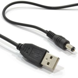
    I was powering with 12v PSU and sometimes 5v USB to barrel jack cable

    eg
    Black cable with USB-A plug and barrel-type DC connector

Topic summary

The discussion centers on the SP530E 5-channel PWM+SPI LED controller, primarily sold by BTF Lighting and generics, and its compatibility with firmware such as WLED and the emerging OpenESP on the ESP32-C3 platform. The device uniquely combines 5 PWM channels with SPI control, raising questions about independent control of SPI LED strips and RGBCW strips. Attempts to use the official BanlanX app and WLED firmware have faced challenges, including security efuse bits preventing reflashing and difficulties achieving stable PWM frequencies beyond a hardcoded 2 kHz in custom WLED builds. The device reportedly uses LEDC for PWM on ESP32-C3, but frequency adjustment functions are not yet implemented in OpenESP firmware. Simulator tools have been updated with features like bistable switches and zoom to aid development. Users report issues with flashing WLED, including boot failures and uncertainty about successful firmware installation, with suggestions to check UART boot logs and use custom WLED builds from Discord repositories. The community is exploring how to handle the device's mixed PWM and SPI LED modes in software, including conditional code checks in OBK PixelAnim. Overall, the SP530E is considered an unusual and somewhat challenging device for LED control development on ESP32-C3, with ongoing efforts to improve firmware support and tooling.
Summary generated by the language model.
ADVERTISEMENT