Elektroda.com
Elektroda.com
X
This content has been translated flag-pl » flag-en View the original version here.
  • Nixie Watch - Open Nixie Project

    Good morning
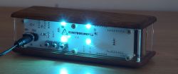
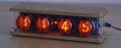
    I wanted to present my next watch project. I have been building watches for years and recently I realized that most of the pieces somehow fell apart and I have the last one left. This motivated me to try to rebuild my collection, hence this project. I called him Open Nixie. Firstly, because it has a modular design, so you do not have to limit yourself to a specific type of displays or a single microcontroller. Second - I make all the materials available.
    The watch consists of three modules on three plates.
    The base module includes the inverter (on MC34063), buttons, power section, ambient light and hour / minute separator.
    The display module includes lamps and drivers (MMBTA42 and 92 pairs for the anodes and circuit 74141 for the cathodes).
    The logic module contains a microcontroller. You can use the Wemos D1 mini module here and the watch then downloads the time via Wi-Fi. I also developed my module with Atmega 328, DS3231 chip and CR1220 / 1225 battery socket for backup. Maybe someday I will develop a different module for fun, for example on MSP430 or STM32.
    The watch was designed to fit in the case from Electronix - aesthetic, easily accessible and at a reasonable price. I designed the interior my way.
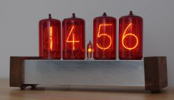
    LC-513 lamps and derivatives. There is also a version for the Z566M, it required special assembly to fit into the housing (also from Electronix :) )
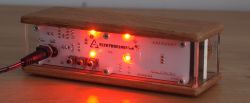
    I built a few pieces, they differ in the logic module and the color of the leds on the back. Leds are and are the way they are, because they are - the privilege of the designer. They do not illuminate the lamps, but the wall / surroundings behind the watch. I know that there are critics of mounting watch diodes - I wasn't sure myself if I would like them - there is a software option to turn them off. Also, choosing the color of the solder mask is just my fantasy. It is dark on the front, so that the plate is unobtrusive, and white on the back, to better diffuse the light from the LEDs.
    The project has its side: http://open-nixie.elektrofanklub.pl/ .
    I add materials to the post, but there is also a github repository: https://github.com/limonit/opennixie
    Nixie Watch - Open Nixie Project Nixie Watch - Open Nixie Project Nixie Watch - Open Nixie Project Nixie Watch - Open Nixie Project Nixie Watch - Open Nixie Project Nixie Watch - Open Nixie Project Nixie Watch - Open Nixie Project
    Nixie Watch - Open Nixie Project Nixie Watch - Open Nixie Project

    Cool? Ranking DIY
    About Author
    Limonit
    Level 13  
    Offline 
    Limonit wrote 138 posts with rating 366, helped 1 times. Live in city Wwa. Been with us since 2007 year.
  • #2
    NIXIE_123
    Level 34  
    1. How is time measured? Inside the CPU in the function and every now and then correction from the ds3231 or maybe the processor only gets time from the ds3231 on a regular basis?

    2. Is there a brightness adjustment of the displays and how is it implemented? Programmatically by function or maybe hardware PWM and multiplexing?
  • #3
    Limonit
    Level 13  
    Ad1. As for the version with ATmega328 and DS3231, the time is measured inside the CPU and updated every 30 minutes from the RTC chip. Since the processor is clocked by an internal RC oscillator, this timing accuracy is quite poor. Therefore, during each update, a calibration is performed (it is exactly a change of the operating range of the counter counting the timer 0 interrupts). Since it works with integers, the calibration itself has some slight inaccuracy. For this reason, the watch only achieves good accuracy after 1-2 hours. Without calibration, the inaccuracy on the hour scale is even several dozen seconds, depending on the device.

    Ad2. There is a brightness control - it's actually a one-step dimming. The display is dynamically controlled - the dimming consists in the imposition of PWM with 50% duty cycle and a period of 200 us. The display has an implemented refreshing function activated every 100 us, which in addition to dimming support, also supports crossfade, i.e. digits diffusion during a change.
  • #4
    lombard1
    Level 13  
    First look at the pictures and it seemed to me that this is a newly developed electroNIXclock Z560M lamp clock.
    Here the thread: https://www.elektroda.pl/rtvforum/topic2858244.html#14293490
    And these are just housings from this source. The Z560M are nice and nice lamps, I have some in stock.
    In the project from electroNIXclock, RTC was realized in ATmange16 using Asynchronous Timer.
    I will add that I made all the clocks from this source.
  • #5
    yego666
    Level 33  
    It looks nice.
    I envy your aesthetic sense.
    My designs have always missed an aesthetic finish, hence my question, where can you buy such nice, stylish enclosures?
  • #6
    lombard1
    Level 13  
    Look for the name electroNIXclock on a well-known auction site ;)
  • #7
    yego666
    Level 33  
    Thank you.
    I've finally found something that will appeal to my nixie clock.
    Once upon a time I made such a clock on the DCF77, but did not have a nice box.
  • #8
    Limonit
    Level 13  
    lombard1 wrote:
    The Z560M are nice and nice lamps, I have some in stock.
    In the project from electroNIXclock, RTC was realized in ATmange16 using Asynchronous Timer.

    The ZM1020 Tesla looks the most beautiful. They have a rare filter shade - very intense red. Unfortunately, I only have 2 pieces. It's hard to find one.

    However, I decided to use a dedicated RTC. As far as I remember, in Electronix the time is maintained on a capacitor for several hours. Since I often turn off my watches for longer periods, that was a bit too little. Lithium batteries will last for many years. I had a CR2032 in some old watch and it continued to work after a dozen or so years. The CR1220 has a few times less capacity, but a few years will definitely work.

    yego666 wrote:
    It looks nice.
    I envy your aesthetic sense.

    Thanks, but unfortunately the housing is not mine. But the fact is - it's great. However, tiles - ordered in China. There are no problems with the colors of the solder mask, there is also no problem with the double-sided description - it is usually included in the standard offer. You can put something on the board, inscriptions, information, logos, etc.
    It was a bit of a chore to fit the design into the housing. I just had the housing before. After the initial measurement, I had to print the board project several times, put it on the Plexiglas housing elements and check if all the holes fit etc. Then correct it and so on. But it worked and the tiles fit in nicely.
  • #9
    yego666
    Level 33  
    Limonit wrote:
    Thanks, but unfortunately the housing is not mine.

    Come on, no one will accuse you of that. What matters is the ability to adapt different elements to achieve a great end result.
    Unfortunately, I do not have it, but I can admire other people's achievements ?
  • #10
    danthe
    Level 30  
    You can put the atmega to sleep, and only on the timer interruption, perform the necessary operations every second, check if the clock is powered externally, and how not to put it to sleep again.
  • #11
    fotomh-s
    Level 24  
    Limonit wrote:
    As for the version with ATmega328 and DS3231, the time is measured inside the CPU and updated every 30 minutes from the RTC chip.

    What is the advantage of this solution over getting the time from the RTC chip in real time?
  • #12
    Judas
    Level 14  
    Nothing. It's inaccurate and the CPU gets boring most of the time anyway. In my solutions, I take the time on a regular basis from RTC and I do not have to worry about accuracy and all kinds of time correction algorithms. If you have a precise quartz with DS, the clock requires practically no adjustment. Even after many years.
  • #13
    marek-zarzycki
    Level 27  
    Would you be able to make a watch with radio synchronization? It is about time synchronization such as wall clocks, etc.
  • #14
    Limonit
    Level 13  
    There is a lot of information that frequent communication with the RTC system causes inaccuracies in timing. My experiences do not confirm this, with both the DS3231 and DS1307. Personally, I had another problem - from time to time the RTC chip lost the correct time and switched to some random time (after switching on). I suspect it may have been related to the power cut during communication. I never confirmed it until the end, maybe there were just some other bugs in the software. I've now done half-hour communication and it has been working perfectly for almost a year. However, it may not be necessary.

    I did not want to do DCF77 - it works very average for me. I have such watches and sometimes they cannot synchronize for several days. Theoretically, it would be possible to make a logic module with a radio receiver, but from what I looked at, these modules are large and the antennas are large and I do not know if it would fit in the housing. I am not able to make such a receiver myself. So theoretically yes, practically not really.
  • #15
    Judas
    Level 14  
    There are several problems with DCF77, of which number 2 is probably "more painful":
    1 - in fact, as my colleague Limonit describes, the dimensions of the receiver, the difficulty of independent amateur winding of the 77.5kHz antenna. You may be tempted to use modules and antennas from Asian cheap watches.
    2 - interference from the HV converter. A working converter (as in this design) sows good radio interference, and this is the basis for DCF communication. The topic was raised many times on various forums and no one came up with a reasonable solution. Shielding the converter, moving the DCF antenna away from the clock, etc. are prostheses.

    Synchronization with the transmitter is poor in our area even without this interference from the converter. I made one watch with DCF synchronization, but after many experiments I came to the point that the receiver with the DCF antenna is on a 1.5 m shielded cable :) By design, the software should do full-hour synchronization. By manipulating the antenna alignment, I was able to achieve the correct 18/24 timing.
  • #16
    lombard1
    Level 13  
    I confirm the problem number 2 in the case of the inverter.
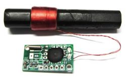
    However, I do not agree with problem 1, I use DCF77 receivers similar to the type from the photo and I have no problem with signal reception and its synchronization.
    In a building through several walls and tested in the eastern part of the country.
    However, I note that with a different type of clock.
    And through the appropriate microprocessor software, via RS232 on the terminal, I am able to track the moment of synchronization.
    RS232 signal monitoring is only an option for control.
    The modules in the photo are currently on sale, they are tuned and you don't need to buy Asian cheap watches to get them ;)
    Nixie Watch - Open Nixie Project

    Consider using the ESP8266 chipset for NTP time synchronization.
  • #17
    fotomh-s
    Level 24  
    Limonit wrote:
    There is a lot of information that frequent communication with the RTC system causes inaccuracies in timing. My experiences do not confirm this, with both the DS3231 and DS1307.


    It's probably such a myth, the whole idea of RTC systems is to measure time correctly. I do not understand what would be the reason for this, reading the register like any other, how would it affect the operation of the RTC and its timing?
  • #18
    Limonit
    Level 13  
    lombard1 wrote:
    The use of the ESP8266 chip for time synchronization with NTP may be considered.

    This solution is already there. The watch has a removable logic module and fits the Wemos D1 mini which has ESP8266 and syncs via NTP.
    I programmed it in Arduino, the problem is that a lot of things are still done there in the background and sometimes it is not easy to do with dynamic lamp control. As a result, sometimes the display flashes for a moment.
  • #19
    yego666
    Level 33  
    Judas wrote:
    1 - in fact, as my colleague Limonit describes, the dimensions of the receiver, the difficulty of independent amateur winding of the 77.5kHz antenna. You may be tempted to use modules and antennas from Asian cheap watches.

    There is no need to use Chinese clocks.
    There is a 2002A kit based on the U4221B chip, which is a ready-made DCF signal receiver. I use one in my NIXIE clocks and there have never been problems with them.
    Of course, it "catches" the DCF signal more often in the west of the country, but also in Warsaw it does it several times a day, which is quite enough.
    When there is no synchronization, the processor running on 2 ^ 32 Hz quartz measures the time itself and I calibrated it until the weekly deviation was lower than 1 second.

    Judas wrote:
    2 - interference from the HV converter. A working converter (as in this design) sows good radio interference, and this is the basis for DCF communication. The topic was raised many times on various forums and no one came up with a reasonable solution. Shielding the converter, moving the DCF antenna away from the clock, etc. are prostheses.

    I solved it in such a way that the display, and hence the converter, are triggered by the PIR detector.
    When the inverter is not working, the processor is powered by 40F supercapacitors, which is enough for about 14 hours of operation. Then the DCF receiver usually catches synchronization. Of course, the processor starts charging the supercapacitors when they already have low voltage. If by any chance there is no voltage in the network, the clock stops working out of hunger. When the voltage returns, the clock recharges and synchronizes with the DCF signal after some time. It is quite enough for me. Moreover, there has never been a time when the clock starved to death.
  • #20
    pawelr98
    Level 39  
    Since, according to the website, the power supply is from 10-12V, why is the colleague the archaic 34063 used instead of the UC3843, which is dedicated to such applications?
    We immediately have a built-in mosfet driver and we do not need to add transistors to control the gate.
    In addition, the resistor measuring the key current may have a lower value, which increases the efficiency of the converter.

    People got 34063/555 in nixie designs clung to when there are other popular ICs that are much better suited for this purpose.
  • #21
    Limonit
    Level 13  
    100% right. I did not make any sense.
  • #22
    pawelr98
    Level 39  
    Judas wrote:
    2 - interference from the HV converter. A working converter (as in this construction) sows good radio interference, and DCF communication is based on such interference. The topic was raised many times on various forums and no one came up with a reasonable solution. Shielding the converter, moving the DCF antenna away from the clock, etc. are prostheses.


    The problem can be solved differently by simply using the power supply directly from the 230V mains.
    But then the 74141 is unlikely to be used for this purpose because it simply cannot withstand voltage (they can withstand some 50-60V as far as I remember). Unless we use a transformerless linear power supply and limit the voltage to 180-200VDC. Otherwise, you need CD4028 + MPSA42 row, or in another version, some ready-made driver with high-voltage keys for the 250-300V.
  • #23
    NIXIE_123
    Level 34  
    Limonit wrote:
    dimming is the imposition of PWM with 50% fill and 200 us period

    [syntax=c]static unsigned char cntr = 0;
    if (!dim || (++cntr & 1)) {
    if(++currentTube > 3) currentTube=0;

    if (currentTube == 0) {
    TUBE1PORT |= 1
  • #24
    Limonit
    Level 13  
    You could say nowhere.
    The variable is incremented and then the least significant bit is taken for comparison, which is alternately 0 and 1:
    ++cntr & 1
  • #25
    NIXIE_123
    Level 34  
    Can I only hear the silent multiplexing of lamps? Especially at night.
  • #26
    yego666
    Level 33  
    I can't hear anything like that in my clocks, so you either have very loud transistors or you have wonderful hearing.
    I recommend going to either an ENT specialist or an exorcist ;)
  • #27
    Krzysztof Kamienski
    Level 43  
    yego666 wrote:
    I recommend going to either an ENT specialist or an exorcist
    And I do not. I did not go into the design, but on the 6th and 8th photos I see a choke, probably a converter, and it may sound some hum with a variable load (cathode multiplexing), so more faith in Mozart's Ear please! :D
  • #28
    pawelr98
    Level 39  
    Oh you can hear sometimes, young people can hear at 20kHz.

    I have a nixie watch and used a regular 9V impulse plug power supply for it.
    It was really annoying at night, because the power supply "chirped" in time with the lighting of the fluorescent lamps (every second).
    Until I changed to a classic 12V + 7809 transformer and finally blissful silence.
    On medium wave radio, however, you can still hear how the lighting of the fluorescent lights causes changes in the nature of the interference.
    A primitive inverter for ne555 (I bought such a kit once, I would never have done such a crap) in the air.

    Impulse converters when they are kicked or the coils have not been secured, they will "sing".

    Therefore, if you have such an option, powering directly from the mains is the most convenient, with a minimum of elements, and at the same time you can make the current more independent of the lamp and the currently lit digit, because the series resistance is higher.
  • #29
    NIXIE_123
    Level 34  
    Unusual question, so I reckoned with stupid and mocking answers.
    I did not write that it is about 4x z566m + 2x z573m.
    With 6x IN-12s, tube chirping was almost nil.
    The converter is not, it gives power on a long cable.
    The sound decreases as I turn the anode voltage, but the brightness also decreases.
    These are the vibrations of the wires inside the lamps. Even taking one in your hand and turning it, you can hear them move

    Quote:
    Das Multiplexen der Anzeige bringt Nachteile mit sich, die hier nicht verschwiegen werden sollen:
    1.es produziert Störungen, die sich negativ auf den DCF-Empfang in unmittelbarer Nähe auswirken und
    2. es läuft nicht geräuschlos ab; die Röhren zirpen ganz leicht.

    tłumacz google wrote:
    Display multiplexing has drawbacks that should not be hidden here:
    1. Produces interference that has a negative effect on DCF reception in the immediate vicinity of and
    2. not running quietly; the pipes chirps very easily.

    Source: http://stefankneller.de/elektronik/nixieuhr/nixiebeschreibung.html
  • #30
    Limonit
    Level 13  
    I also hear lamps sometimes.
    At the stage of programming, it is one of the factors in selecting the refresh rate of displays. It is almost certainly the vibrations of the electrodes caused by the electrostatic effect. The vibrations are transmitted to the bulb and in some frequency ranges the entire lamp resonates. The same thing happens in the VFD lamps.
    The effect can be reduced by manipulating the sweep frequency of the displays.