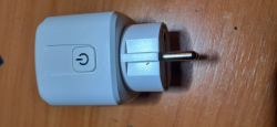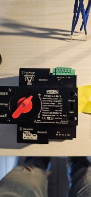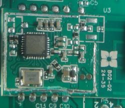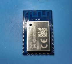
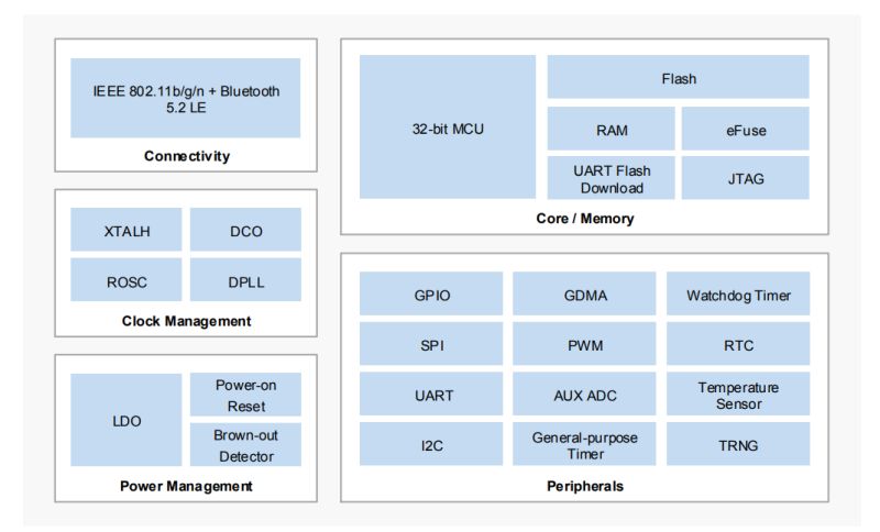
T1 (BK7238) is a Tuya Wi-Fi 802.11b/g/n and Bluetooth 5.2 LowEnergy (LE) single-chip designed for low power and compact size IoT products. T1 is used by T1-M, T1-U-HL, T1-3S, T1-LC5-HL modules. T1 features 32-bit MCU running at up to 160 MHz, 2 MB SiP Flash, 288 KB RAM and 4-byte eFuse. It runs on 2.7 to 3.6 V supply. T1 peripherals include:
- GPIOs: 19 in QFN32, 9 in QFN20
- 1x SPI
- 2x UART: 1 with Flash download support
- 1x I2C
- 1x general-purpose DMA controller (GDMA) with 6 channels
- 6x 32-bit PWM channel
- 10-bit AUX ADC, up to 6 channels
- 6x general-purpose 32-bit timer
- 1x watchdog timer (WDT)
- 1x real-time counter (RTC)
- 1x temperature sensor
- 1x true random number generator (TRNG)
In this topic, I will show the T1 chip pinouts, then I will move to common T1 Tuya modules, and finally I'll show how it can be flashed with open source firmware.
Why change firmware?
Changing firmware allows you to:
- run device free from the cloud (privacy-respecting method)
- pair it with Home Assistant (easily with HASS Discovery)
- configure advanced automations with OBK scripting or Berry
- add mechanisms not possible with Tuya (Tasmota Device Groups, etc)
- add new sensors, buttons and other peripherals
- and much more
Let's start with considering T1 pinouts. The most important pins for flashing are UART1 (TX1 and RX1), which are used for programming, and TX2, which is a debug log output at 115200.
T1 QFN32 Pinout and Descriptions:
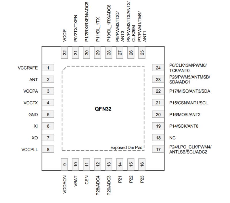
| Pin # | Name | I/O | Type | Description | 1 | VCCRXFE | - | Analog input | RF receiver power supply | 2 | ANT | - | RF | 2.4 GHz RF signal port | 3 | VCCPA | - | Analog input | RF PA power supply | 4 | VCCTX | - | Analog input | RF Transmitter power supply | 5 | GND | - | GND | Ground | 6 | XI | - | Analog input | 26 MHz crystal input | 7 | XO | - | Analog output | 26 MHz crystal output | 8 | VCCPLL | - | Analog input | RF PLL power supply | 9 | VDDAON | - | Analog output | Always-on/digital LDO output | 10 | VBAT | - | Analog input | Chip power supply | 11 | CEN | - | Analog input | Chip enable, active high | 12 | P28/ADC4 | I/O | Digital/Analog | GPIO28 / ADC4 | 13 | P20/ADC3 | I/O | Digital/Analog | GPIO20 / ADC3 | 14 | P21 | I/O | Digital | GPIO21 | 15 | P22 | I/O | Digital | GPIO22 | 16 | P23 | I/O | Digital | GPIO23 | 17 | P24/LPO_CLK/PWM4/ANTLSB/SCL/ADC2 | I/O | Digital/Analog | GPIO24 / 32 kHz clock output / PWM4 (diff w/ PWM5) / BT LE antenna select (LSB) / I2C: SCL / ADC2 | 18 | NC | - | NC | No connect | 19 | P14/SCK/ANT0 | I/O | Digital | GPIO14 / SPI: SCK / BT LE antenna select 0 | 20 | P16/MOSI/ANT2 | I/O | Digital | GPIO16 / SPI: MOSI / BT LE antenna select 2 | 21 | P15/CSN/ANT1/SCL | I/O | Digital | GPIO15 / SPI: CSN / BT LE antenna select 1 / I2C: SCL | 22 | P17/MISO/ANT3/SDA | I/O | Digital | GPIO17 / SPI: MISO / BT LE antenna select 3 / I2C: SDA | 23 | P26/PWM5/ANTMSB/SDA/ADC1 | I/O | Digital/Analog | GPIO26 / PWM5 (diff w/ PWM4) / BT LE antenna select (MSB) / I2C: SDA / ADC1 | 24 | P6/CLK13M/PWM0/TCK/ANT0 | I/O | Digital | GPIO6 / 26 MHz clk (รท1/2/4/8) / PWM0 (diff w/ PWM1) / JTAG: TCK / BT LE antenna select 0 | 25 | P7/PWM1/TMS/ANT1 | I/O | Digital | GPIO7 / PWM1 (diff w/ PWM0) / JTAG: TMS / BT LE antenna select 1 | 26 | P8/PWM2/TDI/ANT2/CLK26M | I/O | Digital | GPIO8 / PWM2 (diff w/ PWM3) / JTAG: TDI / BT LE antenna select 2 / 26 MHz clk output | 27 | P9/PWM3/TDO/ANT3 | I/O | Digital | GPIO9 / PWM3 (diff w/ PWM2) / JTAG: TDO / BT LE antenna select 3 | 28 | P10/DL_1RX/ADC6 | I/O | Digital/Analog | GPIO10 / UART1: RX (Flash DL) / ADC6 | 29 | P11/DL_1TX | I/O | Digital | GPIO11 / UART1: TX (Flash DL) | 30 | P1/2RX/RXEN/ADC5 | I/O | Digital/Analog | GPIO1 / UART2: RX / RX enable / ADC5 | 31 | P0/2TX/TXEN | I/O | Digital | GPIO0 / UART2: TX / TX enable | 32 | VCCIF | - | Analog input | IF power supply | Die pad | GND_SLUG | - | GND | Ground |
T1 QFN20 Pinout and Descriptions:
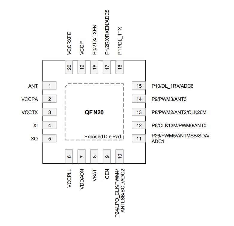
| Pin # | Name | I/O | Type | Description | 1 | ANT | - | RF | 2.4 GHz RF signal port | 2 | VCCPA | - | Analog input | RF PA power supply | 3 | VCCTX | - | Analog input | RF Transmitter power supply | 4 | XI | - | Analog input | 26 MHz crystal input | 5 | XO | - | Analog output | 26 MHz crystal output | 6 | VCCPLL | - | Analog input | RF PLL power supply | 7 | VDDAON | - | Analog output | Always-on/digital LDO output | 8 | VBAT | - | Analog input | Chip power supply | 9 | CEN | - | Analog input | Chip enable, active high | 10 | P24/LPO_CLK/PWM4/ANTLSB/SCL/ADC2 | I/O | Digital/Analog | GPIO24, 32 kHz clock output, PWM4 (differential with PWM5), Bluetooth LE antenna select (LSB), I2C: SCL, ADC2 | 11 | P26/PWM5/ANTMSB/SDA/ADC1 | I/O | Digital/Analog | GPIO26, PWM5 (differential with PWM4), Bluetooth LE antenna select (MSB), I2C: SDA, ADC1 | 12 | P6/CLK13M/PWM0/ANT0 | I/O | Digital | GPIO6, 26 MHz clock output (divided by 1/2/4/8), PWM0, Bluetooth LE antenna select 0 | 13 | P8/PWM2/ANT2/CLK26M | I/O | Digital | GPIO8, PWM2 (differential with PWM3), Bluetooth LE antenna select 2, 26 MHz clock output | 14 | P9/PWM3/ANT3 | I/O | Digital | GPIO9, PWM3 (differential with PWM2), Bluetooth LE antenna select 3 | 15 | P10/DL_1RX/ADC6 | I/O | Digital/Analog | GPIO10, UART1: RX (Flash download support), ADC6 | 16 | P11/DL_1TX | I/O | Digital | GPIO11, UART1: TX (Flash download support) | 17 | P1/2RX/RXEN/ADC5 | I/O | Digital/Analog | GPIO1, UART2: RX, RX enable, ADC5 | 18 | P0/2TX/TXEN | I/O | Digital | GPIO0, UART2: TX, TX enable | 19 | VCCIF | - | Analog input | IF power supply | 20 | VCCRXFE | - | Analog input | RF receiver power supply | Die pad | GND_SLUG | - | GND | Ground |
T1 internal diagram:
That was information about T1, but T1 often comes in form of modules. Here are most common T1 modules.
T1-M Module Pinout
T1-M is a T1 (BK7238) equivalent of WB2S/CB2S/TYWE2S. It exposes PWM, ADC, and UART 1. UART 2 is on the module back.
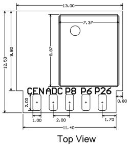
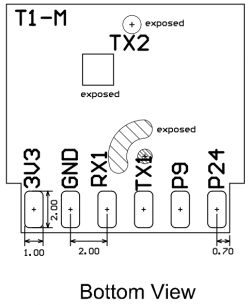
| Pin No. | Symbol | I/O type | Description | 1 | 3V3 | P | 3.3V power pin. | 2 | P26 | I/O | Support hardware PWM, corresponding to Pin 11 on the IC. | 3 | GND | P | Ground pin. | 4 | P6 | I/O | Support hardware PWM, corresponding to Pin 12 on the IC. | 5 | RX1 | I/O | UART_RX1 to receive user data, P10 corresponding to Pin 15 on the IC. | 6 | P8 | I/O | Support hardware PWM, corresponding to Pin 13 on the IC. | 7 | TX1 | I/O | UART_TX1 to send user data, P11 corresponding to Pin 16 on the IC. | 8 | ADC | I/O | ADC pin, GPIO 1, corresponding to Pin 17 on the IC. | 9 | P9 | I/O | Support hardware PWM, corresponding to Pin 14 on the IC. | 10 | CEN | I/O | The reset pin, active low, and pulled up internally. Corresponding to Pin 9 on the IC. | 11 | P24 | I/O | Support hardware PWM, corresponding to Pin 10 on the IC. |
T1-3S Module Pinout
T1-3S is a T1 (BK7238) equivalent of CB3S/WB3S/TYWE3S.
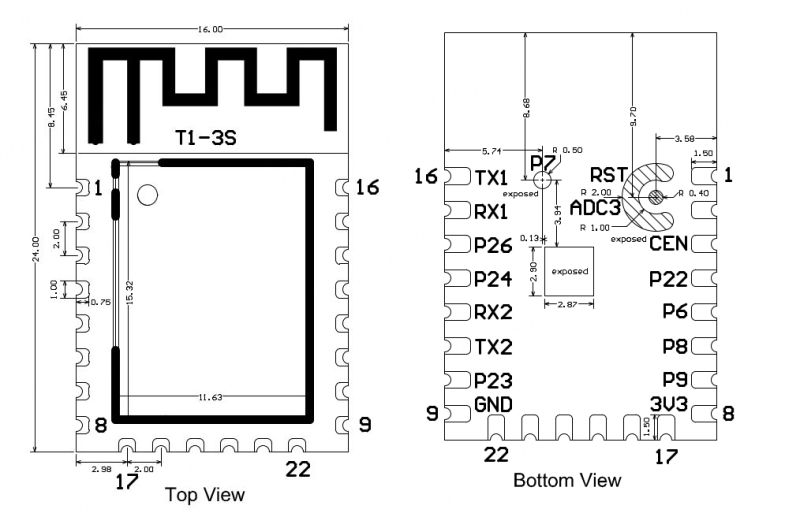
| Pin No. | Symbol | I/O type | Feature | 1 | RST | I | The low-level reset pin, active high, and pulled up internally, corresponding to CEN on the IC. | 2 | ADC3 | I/O | ADC pin, corresponding to P20 on the IC. | 3 | CEN | I | Enable pin, pulled up internally. When externally pulled low, it can be used as a reset pin. | 4 | P22 | I/O | GPIO_22, corresponding to P22 on the IC. | 5 | P6 | I/O | GPIO_6, corresponding to P6 on the IC. Support hardware PWM0. | 6 | P8 | I/O | GPIO_8, corresponding to P8 on the IC. Support hardware PWM2. | 7 | P9 | I/O | GPIO_9, corresponding to P9 on the IC. Support hardware PWM3. | 8 | 3V3 | P | Power supply pin (DC 3.3V). | 9 | GND | P | Ground pin. | 10 | P23 | I/O | GPIO_23, corresponding to P23 on the IC. | 11 | TX2 | I/O | UART2_TXD (used for log printing), corresponding to P0 on the IC. | 12 | RX2 | I/O | UART2_RXD (used for log printing), corresponding to P1 on the IC. | 13 | P24 | I/O | GPIO_24, corresponding to P24 on the IC. Support hardware PWM4. | 14 | P26 | I/O | GPIO_26, corresponding to P26 on the IC. Support hardware PWM5. | 15 | RX1 | I/O | UART1_RXD to receive the user data, corresponding to P10 on the IC. | 16 | TX1 | I/O | UART1_TXD to transmit the user data, corresponding to P11 on the IC. |
T1-LC5-HL
T1-LC5-HL is a T1 (BK7238) equivalent of CBLC5, WBLC5.
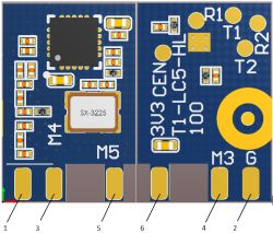
| Pin No. | Symbol | I/O type | Description | 1 | ANT | O | Pin for the external antenna pad. | 2 | G | P | Ground. | 3 | M4 | I/O | Support hardware PWM, corresponding to P24 on the IC. | 4 | M3 | I/O | Support hardware PWM, corresponding to P9 on the IC. | 5 | M5 | I/O | Support hardware PWM, corresponding to P26 on the IC. | 6 | 3V3 | P | Power pin |
| Symbol | I/O type | Description | R2 | I/O | UART2_RX to receive the logs, corresponding to P12 on the IC. | T2 | I/O | UART2_TX to transmit the logs, corresponding to P0 on the IC. | R1 | I/O | UART1_RX to receive the user data, corresponding to P10 on the IC. | T1 | I/O | UART1_TX to transmit the user data, corresponding to P11 on the IC. | CEN | I | The reset pin, active low, and pulled up internally. |
T1-U-HL
T1-U-HL is a T1 (BK7238) equivalent of CBU.
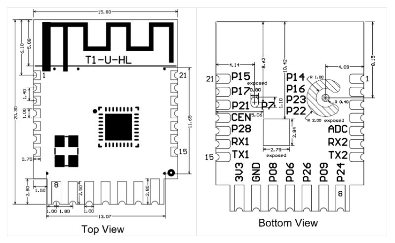
| Pin No. | Symbol | I/O type | Description | 1 | P14 | I/O | A normal GPIO pin, corresponding to Pin 19 on the IC. It can be reused as SPI_SCK. | 2 | P16 | I/O | A normal GPIO pin, corresponding to Pin 20 on the IC. It can be reused as SPI_MOSI. | 3 | P23 | I/O | A normal GPIO pin, corresponding to Pin 16 on the IC. | 4 | P22 | I/O | A normal GPIO pin, corresponding to Pin 15 on the IC. | 5 | ADC | I/O | An ADC pin, corresponding to P20 (Pin 13) on the IC. | 6 | RX2 | I/O | UART_RX2, corresponding to P1 (Pin 30) on the IC. | 7 | TX2 | I/O | UART_TX2 to print logs, corresponding to P0 (Pin 31) on the IC. | 8 | P24 | I/O | Support hardware PWM4, corresponding to Pin 17 on the IC. | 9 | P9 | I/O | Support hardware PWM3, corresponding to Pin 27 on the IC. | 10 | P26 | I/O | Support hardware PWM5, corresponding to Pin 23 on the IC. | 11 | P6 | I/O | Support hardware PWM0, corresponding to Pin 24 on the IC. | 12 | P8 | I/O | Support hardware PWM2, corresponding to Pin 26 on the IC. | 13 | GND | P | Ground pin. | 14 | 3V3 | P | 3.3V power pin. | 15 | TX1 | I/O | UART_TX1 to send user data, corresponding to P11 on the IC (corresponding to Pin 29 on the IC). For more information about MCU general integration, see Hardware Design of CBx Module. | 16 | RX1 | I/O | UART_RX1 to receive user data, corresponding to P10 on the IC (corresponding to Pin 28 on the IC). For more information about MCU general integration, see Hardware Design of CBx Module. | 17 | P28 | I/O | A normal GPIO pin, corresponding to Pin 12 on the IC. | 18 | CEN | I/O | The reset pin, active low, and pulled up internally. It is compatible with the designs of other modules. Corresponding to Pin 11 on the IC. | 19 | P21 | I/O | A normal GPIO pin, corresponding to Pin 14 on the IC. | 20 | P17 | I/O | A normal GPIO pin, corresponding to Pin 22 on the IC. It can be reused as SPI_MISO. | 21 | P15 | I/O | A normal GPIO pin, corresponding to Pin 21 on the IC. It can be reused as SPI_CS. |
How to flash T1 and T1 modules?
Flashing T1 (BK7238) is very similar to flashing BK7231T/BK7231N, so please check our BK7231T/BK7231N tutorials. I will provide here just a short version of the guide.
Remember to make 2MB firmware backup before flashing any new software!
Hardware setup
For flashing BK7238, you will need USB to UART converter. Futhermore you will need to provide a good 3.3V power supply, powering WiFi module directly from USB to UART converter may not be enough. I often use external 3.3V LDO like AMS1117-3.3V for this purpose. It's also possible to use onboard LDO if your device has one, then you can connect 5V to the input of the LDO to get 3.3V at the output, as 3.3V is required for WiFi module.
So, you need to connect ground, power (3.3V) and RX/TX to UART 1 port of Beken. Connect TX to RX and RX to TX.
When flashing tools is waiting for reset/getting bus, disconnect 3.3V for a moment and reconnect it.
See our other guides for more information.
Firmware download
Download OBK here:
https://github.com/openshwprojects/OpenBK7231T_App/releases
Get OpenBK7238_QIO_*.bin, as T1 is BK7238.
Remember that in case of Easy Flasher, this is not necessary, as Easy Flasher can automatically download required binary from Github.
Flashing software option 1 - Easy Flasher:
https://github.com/openshwprojects/BK7231GUIFlashTool
Easy Flasher is very simple to use, just run it, select chip (BK7238), use it to download firmware, and then first do flash backup and then write new firmware.
Flashing software option 2 - BKFil:
https://www.elektroda.com/rtvforum/topic4059172.html
https://github.com/openshwprojects/FlashTools/tree/main/Beken
Sample log:
 cmdline: |D:/Instalki/Open BK7321/BEKEN_BKFIL_V2.1.6.0_20231123/bk_loader.exe download -p 6 -b 1500000 --uart_type OTHER --mainBin-multi D:/Instalki/Open BK7321/BK7231GUIFlashTool-v49/firmwares/OpenBK7238_QIO_1.18.140.bin@0x0-0x132000 --fast_link 1 |
 bk_loader version 2.1.6.0: build @Nov 23 2023 11:23:40
 2025-07-27 18:58:55.833    Current port : COM6 + BaudRate : 115200 connect success
 2025-07-27 18:58:56.034    do_reset_signal
 2025-07-27 18:58:56.034    Getting Bus...
 2025-07-27 18:58:58.905    Gotten Bus...
 2025-07-27 18:58:59.049    Got ChipId: 0x7238

 2025-07-27 18:58:59.049    Current Chip is : BK7238
 2025-07-27 18:58:59.081    Current baudrate : 1500000 success
 2025-07-27 18:58:59.112    rxf-uid : 45 53 4d 39 38 38 00 07 00 ab 4a 52 01 20 ad 78
 2025-07-27 18:58:59.112    Got FLashMID: 0x154285

 2025-07-27 18:58:59.116    Unprotecting Flash
 2025-07-27 18:58:59.144    Unprotected Flash ->pass
 2025-07-27 18:58:59.144    [ 0 ] file_path : D:/BK7231GUIFlashTool-v49/firmwares/OpenBK7238_QIO_1.18.140.bin
 2025-07-27 18:58:59.144    [ 0 ] file_length : 0x132000 (1224 KB)
 2025-07-27 18:58:59.144    [ 0 ] file_crc : 0x8f7900f9
 2025-07-27 18:58:59.144    Begin EraseFlash
 2025-07-27 18:58:59.147    Start 4K Erase
 2025-07-27 18:58:59.147    End 4K Erase
 2025-07-27 18:58:59.147    Start 64K Erase
 2025-07-27 18:59:00.210    End 64K Erase
 2025-07-27 18:59:00.210    EraseFlash ->pass
 2025-07-27 18:59:00.213    Begin WriteFlash...
 2025-07-27 18:59:10.402    WriteFlash ->pass
 2025-07-27 18:59:10.402    Begin read CRC
 2025-07-27 18:59:13.254    CRC_Verify ->pass
 2025-07-27 18:59:13.347    Enprotect pass
 2025-07-27 18:59:13.380    Boot_Reboot

 2025-07-27 18:59:13.767    Total Test Time : 14.861 s
 2025-07-27 18:59:13.767    Writing Flash OK
Troubleshooting
Whole process is similar to BK7231 flashing, so as usual:
- try to swap RX and TX
- make sure you power module with good 3.3V supply
- shorten the wires
- try using CEN to reset instead of power disconnection (short CEN to ground for 0.1s)
- try different baud rate
- try different USB to UART converter
Related video guides
These are for BK7231T/BK7231N, but process for BK7238/T1 is the same, just do flashing as specified above.
Sample device boot log from Tuya firmware
This was taken from TX2 pin at 115200 baud.
 prvHeapInit-start addr:0x415228, size:175576
[Flash]id:0x852015
bk_timer_init exit
spi_init exit
sctrl_sta_ps_init
**********tuya_upgrade_main need upgrade? [255]**********
cset:0 0 0 0
[FUNC]rwnxl_init
IP Rev: 431458e2
tkl_ethernetif_init
tkl_[bk]tx_txdesc_flush
ex_txdesc_flush
[FUNC]intc_init
[FUNC]calibration_main
gpio_level=1,txpwr_state=15
device_id=0x22068000
[01-01 00:00:00 ty E][4164][log_seq.c:884] logseq empty
[01-01 00:00:00 ty N][4164][ty_sys.c:277] sdk_info:< TuyaOS V:3.8.31 BS:40.00_PT:2.3_LAN:3.5_CAD:1.0.5_CD:1.0.0 >
< BUILD AT:2024_12_26_11_42_43 BY ci_manage FOR tuyaos-iot AT T1 >
IOT DEFS < WIFI_GW:1 DEBUG:0 KV_FILE:0 LITTLE_END:1 SL:0 OPERATING_SYST[01-01 00:00:00 ty N][4164][ty_sys.c:278] name:oem_t1_irbox_mol_ty:0.0.5
[01-01 00:00:00 ty N][4164][ty_sys.c:279] firmware compiled at Feb 25 2025 21:21:43
[01-01 00:00:00 ty N][4164][ty_sys.c:280] system reset reason:[0]
[01-01 00:00:00 ty N][4164][simple_flash_protected.c:86] init protected data length 715 wr_cnt 14
[01-01 00:00:00 ty N][4164][simple_flash.c:447] key_addr: 0x1f5000   block_sz 4096
[01-01 00:00:00 ty N][4164][simple_flash.c:533] get key:
calibration_main over
flash txpwr table:0xf
dif g and n20 ID in flash:4
read txpwr tab from flash success
calibrate low value:[465]
calibrate high value:[8d3]
temp in flash is:256
lpf_i &[01-01 00:00:00 ty N][4 0:00:00 ty N][4164][td164][tdd_button_gpio.c:d_button_gpio.c:199] td199] tdd_gpio_button_regd_gpio_button_register ister succ
succ
found[01-01 00:00:00 ty N][4  00:00:00 ty N][4164][164][ty_app_ir_oem_confty_app_ir_oem_config.c:ig.c:56] --->long_press56] --->long_press_time:_time:3
[01-01 00:00:03
use xtal:51
xtal_ca0 ty N][4164][tuya_tls.li:51
--init_xtal = 51c:911] uni_random_init.
[FUNC]ps_init
[FUNC]..
func_init_extended OVER!!!

start_type:0
[01-01 00:00:00 ty N][400 ty N][4164][tuya_tls164][tuya_tls.c:354] tu.c:354] tuya_tls_rand_iya_tls_rand_init ok!
nit ok!
Version:
app_init finished
[01-01 00:00:00 ty E][416e][api_lib.c:227] LWIP_NETCONN_THREAD_SEM_FREE:not find thread sem

[01-01 00:00:00 ty N][4164][tuya_svc_devos.c:319] gw_cntl->gw_wsm.stat:2
rw_ieee80211_set_country code:
code: CN
channel: 1 - 13
mode: MANUAL
bk_wlan cca closed
!! tkl_wifi_station_fast_connect
>>> mhdr_set_station_status_cb
>>> _wifi_station_status_cb 0
wlan_clear_fast_connect_info
>>> mhdr_set_station_status 0
>>> _wifi_station_status_cb 0
[sa_sta]MM_RESET_REQ
[bk]tx_txdesc_flush
[sa_sta]ME_CONFIG_REQ
[sa_sta]ME_CHAN_CONFIG_REQ
[sa_sta]MM_START_REQ
fast_connect
sizeof(wpa_supplicant)=928
hapd_intf_add_vif,type:2, s:0, id:0
wpa_dInit
hapd_intf_ioctl:939
hapd_intf_ioctl:939
hapd_intf_ioctl:939
hapd_intf_ioctl:939
hapd_intf_ioctl:939
hapd_intf_ioctl:939
netif_is_added: 0x40c418
netif_is_added: 0x40c3d0
net_wlan_add_netif already exist!, vif_idx:0
mac 80:64:7c:21:ff:7b
net_wlan_add_netif done!, vif_idx:0
me_mgmt_tx chan no avail
cipher2security 2 2 24 8
cipher2security 2 2 24 8
wpa_supplicant_connect
Cancelling sca[01-01 01:00:0chan avail
n ty N][4164][tuya_wi0 ty N][4164][tuya_wififi_status.c:167] cur st_at:5  0x0 -->>
status.c:167] cur stat:5  0x0wpa_driver_associate: a -->>
[01-01 01:00:00 u64][tuya_wifi_status.c:ty N][4164][tuya_wifi_s169] wifi netstat changtatus.c:169] wifi netsted to:5  -->>
>>> mhdr_set_station_status 3
>>> _wifi_station_status_cb 3
at changed to:5found scan rst rssi -38 > -50
bssid 74:da:88:a5:9e:fb, cap_info 0x1031, BI 100, ssid DOM-1
sm_auth_send:1
  -->>
[01-01 01:00:00 ty N][4164][mf_test.c:276] have actived over 15 min, not enter mf_init
[01-01 01:00:00 ty N][4164][ty_sys.c:343] mf_init succ
[01-01 01:00:00 ty N][4164][ty_sys.c:63] have actived over 15min, don't scan prod test ssid
[01-01 01:00:00 ty N][4164][tuya_iot_wifi_api.c:307] wifi soc init. pid:keycmhjv873dhvsn firmwarekey:keycmhjv873dhvsn ver:0.0.5
[01-01 01:00:00 ty N][4164][tuya_wifi_link.c:86] start wifi link params validate, nc_tp:9 md:3
[01-01 01:00:00 ty N][4164][tuya_wifi_link.c:108] gw_wsm.nc_tp:9
[01-01 01:00:00 ty N][4164][tuya_wifi_link.c:109] gw_wsm.md:3
[01-01 01:00:00 ty N][4164][tuya_svc_devos.c:547] Last reset reason: 0
[01-01 01:00:00 ty N][4164][tuya_svc_devos.c:376] gw_cntl->gw_if.abi:0 input:0
[01-01 01:00:00 ty N][4164][tuya_svc_devos.c:377] gw_cntl->gw_if.product_key:keycmhjv873dhvsn, input:keycmhjv873dhvsn
[01-01 01:00:00 ty N][4164][tuya_svc_devos.c:378] gw_cntl->gw_if.tp:0, input:0
[01-01 01:00:00 ty N][4164][tuya_svc_devos.c:381] gw_cntl->gw_if.firmware_key:keycmhjv873dhvsn, input:keycmhjv873dhvsn
[01-01 01:00:00 ty N][4164][tuya_svc_devos.c:580] enter success_proc
[01-01 01:00:00 ty N][4164][tuya_svc_devos.c:583] serial_no:80647c21ff7b
[01-01 01:00:00 ty N][4164][tdl_ir_dev_manage.c:1441] Set ir recv task stack size: 4096
[01-01 01:00:00 ty N][41e5][tuya_bt_link.c:63] bt startup attr:ff
[01-01 01:00:00 ty N][41e5][tuya_ble_svc.c:1204] upd product_id type:1 keycmhjv873dhvsn
[01-01 01:00:00 ty N][4164][tdl_binitial BLE...
ble mac:80-64-7c-21-ff-7c
rwip_heap_env addr:0x42e4e8 size:972
rwip_heap_msg addr:0x42e8c0 size:3208
rwip_heap_non_ret addr:0x42f550 size:668
xvr_reg_init
tx_pwr_idx:41
enter normal mode
uze:668
[01-01 01:00:00 ty N][4285][tbl_ir_cloud_service.c:475] sw timer create success
[01-01 01:00:00 ty N][41a9][ty_app_ir_component.c:78] =================>event_id:3, event_size:0
[01-01 01:00:00 ty N][41e5][tuya_ble_svc.c:1299] ty bt sdk init success finish
[01-01 01:00:00 ty E][41e5][tuya_svc_timer_task.c:1376] read timer_full_key failed
[01-01 01:00:00 ty N][41e5][tuya_svc_devos.c:231] __devos_init_evt success
[01-01 01:00:00 ty N][41e5][tuya_svc_devos.c:68] already bind
[01-01 01:00:00 ty N][41e5][tuya_svc_mqtt_client.c:179] [mqtts://m3-eu.lifeaiot.com:8883] mqtt state change 0 -> 1
[01-01 01:00:00 ty N][4329][tuya_svc_mqtt_client.c:1275] mqtt_thread paused
[01-01 01:00:00 ty N][4329][tuya_svc_mqtt_client.c:664] mqtt close
[01-01 01:00:00 ty E][41e5][astro_timer.c:326] astro timer read fail:-6
[01-01 01:00:00 ty E][41e5][astro_timer.c:861] read fail:-6
[01-01 01:00:00 ty E][41e5][tuya_wifi_connect.c:371] wf connect err:-1, ssid:DOM-1
[01-01 01:00:00 ty N][41e5][tuya_wifi_status.c:167] cur stat:5  0x5e64d -->>
[01-01 01:00:00 ty N][41d3][ty_app_main.c:54] Main Module: v1.0.0 (0.0.5)
temp_code:30 - adc_code:245 - adc_trend:[13]:256->[14]:246
init_xtal:51, delta:-1, last_xtal:51
[01-01 01:00:00 ty N][41e5][ble_gap.c:2509] Start Adv
[01-01 01:00:00 ty N][41e5][tuya_ble_svc.c:1386] ble adv updated
auth timeout
SM_DISCONNECTING status=1
>>> mhdr_set_station_status 9
>>> _wifi_station_status_cb 9
RW_EVT_STA_CONNECT_FAILED 9
---------SM_CONNECT_IND_fail
[01-01wpa_supplicant_req plic_scan
Setting scan[reta[retry1] request: 0.100ry1] request: 0.100000 000 sec
sec
wpa_supplicant_scan
wpa_drv_scan
wpa_send_scan_req
>>> mhdr_set_station_status 1
>>> _wifi_station_status_cb 1
ht in scan
scan_start_req_handler
wpa_driver_scan_start_cb
scanu_confirm: status 0, upload_cnt 0, recv_cnt 3, time 204573us, result 0
wpa_driver_scan_cb
Scan completed in 0.202000 seconds
>>> mhdr_set_station_status 2
>>> _wifi_station_status_cb 2
get_scan_rst_null
>>> mhdr_set_station_status 6
>>> _wifi_station_status_cb 6
No suitable network found
wpa_supplicant_req_scan
Setting scan[retry0] request: 5.000000 sec
>>> mhdr_set_station_status_when_reconnect_over 6
>>> _wifi_station_status_cb 6
tkl_wifi_station_connect !!!
Cancelling scan request
sm external auth not in corrent state
>>> mhdr_set_station_status 0
>>> _wifi_station_status_cb 0
wpa_supplicant_req_scan
Setting scan[retry1] request: 0.000000 sec
wpa_supplicant_scan
wpa_drv_scan
wpa_send_scan_req
>>> mhdr_set_station_status 1
>>> _wifi_station_status_cb 1
ht in scan
scan_start_req_handler
wpa_driver_scan_start_cb
scanu_confirm: status 0, upload_cnt 0, recv_cnt 19, time 1326385us, result 0
wpa_driver_scan_cb
Scan completed in 1.322000 seconds
>>> mhdr_set_station_status 2
>>> _wifi_station_status_cb 2
get_scan_rst_null
>>> mhdr_set_station_status 6
>>> _wifi_station_status_cb 6
RW_EVT_STA_CONNECT_FAILED 6
[01-01 01:00:03 ty N][No suitable network fou4nd
nd
wpa_supplicant_req_scan
Setting scan[retry0] request: 5.000000 sec
>>> mhdr_set_station_status_when_reconnect_over 6
>>> _wifi_station_status_cb 6
tkl_wifi_station_connect !!!
Cancelling scan request
sm external auth not in corrent state
>>> mhdr_set_station_status 0
>>> _wifi_station_status_cb 0
wpa_supplicant_req_scan
Setting scan[retry1] request: 0.000000 sec
wpa_supplicant_scan
wpa_drv_scan
wpa_send_scan_req
>>> mhdr_set_station_status 1
>>> _wifi_station_status_cb 1
ht in scan
scan_start_req_handler
wpa_driver_scan_start_cb
scanu_confirm: status 0, upload_cnt 0, recv_cnt 23, time 1326447us, result 0
wpa_driver_scan_cb
Scan completed in 1.322000 seconds
>>> mhdr_set_station_status 2
>>> _wifi_station_status_cb 2
get_scan_rst_null
>>> mhdr_set_station_status 6
>>> _wifi_station_status_cb 6
RW_EVT_STA_CONNECT_FAILED 6
[01-01 01:00:07 ty N][No suitable network fou4nd
nd
wpa_supplicant_
req_scan
Setting scan[retry0] request: 5.000000 sec
>>> mhdr_set_station_status_when_reconnect_over 6
>>> _wifi_station_status_cb 6
tkl_wifi_station_connect !!!
Cancelling scan request
sm external auth not in corrent state
>>> mhdr_set_station_status 0
>>> _wifi_station_status_cb 0
wpa_supplicant_req_scan
Setting scan[retry1] request: 0.000000 sec
wpa_supplicant_scan
wpa_drv_scan
wpa_send_scan_req
>>> mhdr_set_station_status 1
>>> _wifi_station_status_cb 1
ht in scan
scan_start_req_handler
wpa_driver_scan_start_cb
scanu_confirm: status 0, upload_cnt 0, recv_cnt 13, time 1326588us, result 0
wpa_driver_scan_cb
Scan completed in 1.322000 seconds
>>> mhdr_set_station_status 2
>>> _wifi_station_status_cb 2
get_scan_rst_null
>>> mhdr_set_station_status 6
>>> _wifi_station_status_cb 6
RW_EVT_STA_CONNECT_FAILED 6
[01-01 01:00:11 ty N]No suitable network fou[und
nd
wpa_supplicant_req_scan
Setting scan[retry0] request: 5.000000 sec
>>> mhdr_set_station_status_when_reconnect_over 6
>>> _wifi_station_status_cb 6
tkl_wifi_station_connect !!!
Cancelling scan request
sm external auth not in corrent state
>>> mhdr_set_station_status 0
>>> _wifi_station_status_cb 0
wpa_supplicant_req_scan
Setting scan[retry1] request: 0.000000 sec
wpa_supplicant_scan
wpa_drv_scan
wpa_send_scan_req
>>> mhdr_set_station_status 1
>>> _wifi_station_status_cb 1
ht in scan
scan_start_req_handler
wpa_driver_scan_start_cb
scanu_confirm: status 0, upload_cnt 0, recv_cnt 22, time 1326433us, result 0
wpa_driver_scan_cb
Scan completed in 1.322000 seconds
>>> mhdr_set_station_status 2
>>> _wifi_station_status_cb 2
get_scan_rst_null
>>> mhdr_set_station_status 6
>>> _wifi_station_status_cb 6
RW_EVT_STA_CONNECT_FAILED 6
[01-01 01:00:17 tNo suitable network fouyk found
nd
wpa_supplicant_req_scan
Setting scan[retry0] request: 5.000000 sec
>>> mhdr_set_station_status_when_reconnect_over 6
>>> _wifi_station_status_cb 6
tkl_wifi_station_connect !!!
Cancelling scan request
sm external auth not in corrent state
>>> mhdr_set_station_status 0
>>> _wifi_station_status_cb 0
wpa_supplicant_req_scan
Setting scan[retry1] request: 0.000000 sec
wpa_supplicant_scan
wpa_drv_scan
wpa_send_scan_req
>>> mhdr_set_station_status 1
>>> _wifi_station_status_cb 1
ht in scan
scan_start_req_handler
wpa_driver_scan_start_cb
scanu_confirm: status 0, upload_cnt 0, recv_cnt 23, time 1326169us, result 0
wpa_driver_scan_cb
Scan completed in 1.322000 seconds
>>> mhdr_set_station_status 2
>>> _wifi_station_status_cb 2
get_scan_rst_null
>>> mhdr_set_station_status 6
>>> _wifi_station_status_cb 6
RW_EVT_STA_CONNECT_FAILED 6
No suitable network found[01-01 01:00:26 ty N][4
][ta1e5][tal_wifi_recol_wifi_reconnet.c:246] nnet.c:246] wifi statuswifi status changed to  changed to 1, stat: 1
1, stat: 1
wpa_supplic
ant_req_scan
Setting scan[retry0] request: 5.000000 sec
>>> mhdr_set_station_status_when_reconnect_over 6
>>> _wifi_station_status_cb 6
[01-01 01:00:36 ty N][41bd][tal_wifi_reconnet.c:187] wifi reconnet finsh
[01-01 01:00:36 ty N][41bd][tuya_wifi_status.c:167] cur stat:5  0x5e64d -->>
[01-01 01:01:00 ty N][41d3][tuya_wifi_protect.c:1576] device is long time(local:60 cloud:0) offline,stat:3 start wifi backup reconnect
[01-01 01:01:00 ty N][41d3][tuya_wifi_connect.c:455] device is long time(local:60 cloud:0) offline,stat:5 start local reconnect
[01-01 01:01:00 ty N][41d3][tuya_wifi_connect.c:161] reconect func got ssid&passwd , start reconnect
tkl_wifi_station_connect !!!
Cancelling scan request
sm external auth not in corrent state
>>> mhdr_set_station_status 0
>>> _wifi_station_status_cb 0
wpa_supplicant_req_scan
Setting scan[retry1] request: 0.000000 sec
wpa_supplicant_scan
wpa_drv_scan
wpa_send_scan_req
>>> mhdr_set_station_status 1
>>> _wifi_station_status_cb 1
ht in scan
scan_start_req_handler
wpa_driver_scan_start_cb
scanu_confirm: status 0, upload_cnt 0, recv_cnt 13, time 1326383us, result 0
wpa_driver_scan_cb
Scan completed in 1.322000 seconds
>>> mhdr_set_station_status 2
>>> _wifi_station_status_cb 2
get_scan_rst_null
>>> mhdr_set_station_status 6
>>> _wifi_station_status_cb 6
RW_EVT_STA_CONNECT_FAILED 6
[01-01 01:01:02 tyNo suitable network foun  found
d
wpa_supplicant_req_scan
Setting scan[retry0] request: 5.000000 sec
>>> mhdr_set_station_status_when_reconnect_over 6
>>> _wifi_station_status_cb 6
tkl_wifi_station_connect !!!
Cancelling scan request
sm external auth not in corrent state
>>> mhdr_set_station_status 0
>>> _wifi_station_status_cb 0
wpa_supplicant_req_scan
Setting scan[retry1] request: 0.000000 sec
wpa_supplicant_scan
wpa_drv_scan
wpa_send_scan_req
>>> mhdr_set_station_status 1
>>> _wifi_station_status_cb 1
ht in scan
scan_start_req_handler
wpa_driver_scan_start_cb
T1/BK7238 dev board
If you want to run BK7238/T1 code, but don't have any Tuya modules, you can try using NiceMCU XH-WB3S:
https://www.elektroda.com/rtvforum/topic4106397.html
Summary
T1 is a new Tuya WiFi chip based on BK7238 core. T1 can be flashed just like BK7238 with our open source firmware (our multiplatform solution inspired by Tasmota/Esphome) and paired with Home Assistant. Preferred flashing tool is Easy Flasher, but you can also use BKfill if there is some problem. Just remember to make 2MB flash backup first.
Have you encounted any T1 Tuya modules so far? Let us know! We can help you with device setup and integration as well.
Cool? Ranking DIY Helpful post? Buy me a coffee.


