logo elektroda
logo elektroda
X
logo elektroda

[Solved] Why is it that when a PWM signal is applied to the module, full voltage appears at the output?

arkanzzo 435 5
ADVERTISEMENT
Treść została przetłumaczona polish » english Zobacz oryginalną wersję tematu
  • #1 19794675
    arkanzzo
    Level 4  
    Hello.
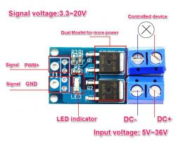
    Has anyone perhaps encountered the case that when I feed a PWM signal to a module (or MOSFET), I always get the full voltage at the output regardless of the PWM fill given? The PWM signal is applied correctly - I checked with a multimeter. The voltage and frequencies agree. This happens regardless of the amplitude of 0 - 3.3V or 0 - 5V. To make it funnier, when I constructed my father an aquarium lamp controlled by PWM via current drivers it all worked correctly. I am attaching an overview diagram and would appreciate any hints. Why is it that when a PWM signal is applied to the module, full voltage appears at the output? .
  • ADVERTISEMENT
  • #2 19794692
    sigwa18
    Level 43  
    Mos fet at high PWM frequencies may not be discharged specifically its gate . Simply turning it off may not be enough because of the capacitance of the gate and the leads. Special mos fet drivers short-circuit the gate to ground or even polarise it with a negative voltage when the transistor is switched off. This discharges the gate faster and the transistor switches off more quickly.
  • ADVERTISEMENT
  • #3 19794785
    michal.zd
    Level 28  
    sigwa18 wrote:
    Mos fet at high PWM frequencies may not be discharged specifically its gate . Simply turning it off may not be enough because of the capacitance of the gate and the leads. Special mos fet drivers short-circuit the gate to ground or even polarise it with a negative voltage when the transistor is switched off. Then they discharge the gate faster and the transistor is switched off faster.


    Yes, a possible reason that it does not close, but I doubt that in this case we are dealing with frequency in MHz.
    To the author, it would be good to show a wiring diagram including the type of transistor, if you don't have an oscilloscope then instead of a MOSFET connect a bipolar one without a lamp with some resistor in the hundreds of ohms to the base and a similar one in the load and then check with a multimeter if it responds to PWM.
    You can also reduce the frequency in the ESP for testing.

    Added after 4 [minutes]: .

    Aaa, one more thing: see the schematic of your ESP board, if there is no filter on the PWM output in the form of a capacitor with a resistor.
  • ADVERTISEMENT
  • #4 19794823
    arkanzzo
    Level 4  
    In my case it is a frequency of 1kHz. I use a ready-made module consisting of 2 MOSFETs designed for just such things: Why is it that when a PWM signal is applied to the module, full voltage appears at the output? .
    At first I thought there was a ground problem but I checked everything and it is ok.
  • ADVERTISEMENT
  • #5 19794909
    michal.zd
    Level 28  
    Ok. Now it's still a matter of finding the schmat of your NodeMcu. There are several versions of this module, so only you know what you have. If there is a filter built into the PWM output, then that is the cause of your problem.
    1kHz is a very baaarry low frequency for the effect mentioned in the second post to have an effect.
    Still, do a trivial test that the two mosfets are working. Just give any pin from the controller a signal with f<1Hz, the lamp should blink at that frequency. Check, we'll rule it out at least.
  • #6 19795471
    arkanzzo
    Level 4  
    Ok thanks gentlemen for your answers. Everything was generally fine only not knowing why without load the multimeter shows such miracles. When a load is connected to the output everything is fine.
ADVERTISEMENT