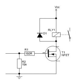
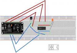
Please help me identify the cause of the diode not lighting up after reproducing the first schematic on the actual board.
On the programming side, this is simply raising the state on the general purpose outputs (D5 and D7).
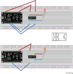
I have not been able to find a better relay in the visualization software, so let's assume that column number 25 on the board is Normally Open (NO), 26 is COM, 30 is Normally Closed (NC) and 31 is the coil.
With the second diagram (using COM and NC) the diode lights up, and this only indicates that current is flowing through the (off) relay.
I measured the voltage between D5 and GND with a multimeter and it is, as would be expected, 3.3V. When measuring the current, the multimeter displays 0.75 (when LOW) and 1 (when HIGH).
Excerpt from the relay specification. I don't know what is important, so I am inserting selected information:
* Nominal coil voltage 3V DC.
* Coil resistance 17Ω
* Coil power consumption 530mW.
* Coil current 176.5mA
This is the LMR2-3D Recoy/RAYEX ELECTRONICS relay, such:
https://www.tme.eu/pl/details/lmr2-3d/przekaz...ktromagn-miniaturowe/recoy-rayex-electronics/
I'm wondering if the NodeMCU is too weak to turn on this relay, or maybe it's another simple beginner's error. The NodeMCU is powered via USB from the computer.
 .
.
On the programming side, this is simply raising the state on the general purpose outputs (D5 and D7).
I have not been able to find a better relay in the visualization software, so let's assume that column number 25 on the board is Normally Open (NO), 26 is COM, 30 is Normally Closed (NC) and 31 is the coil.
With the second diagram (using COM and NC) the diode lights up, and this only indicates that current is flowing through the (off) relay.
I measured the voltage between D5 and GND with a multimeter and it is, as would be expected, 3.3V. When measuring the current, the multimeter displays 0.75 (when LOW) and 1 (when HIGH).
Excerpt from the relay specification. I don't know what is important, so I am inserting selected information:
* Nominal coil voltage 3V DC.
* Coil resistance 17Ω
* Coil power consumption 530mW.
* Coil current 176.5mA
This is the LMR2-3D Recoy/RAYEX ELECTRONICS relay, such:
https://www.tme.eu/pl/details/lmr2-3d/przekaz...ktromagn-miniaturowe/recoy-rayex-electronics/
I'm wondering if the NodeMCU is too weak to turn on this relay, or maybe it's another simple beginner's error. The NodeMCU is powered via USB from the computer.
 .
.


