
Czy wolisz polską wersję strony elektroda?
Nie, dziękuję Przekieruj mnie tam
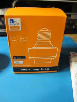
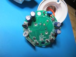
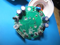
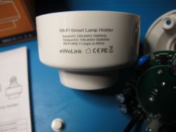
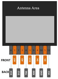
bl602newbie wrote:but it's just a lamp holder
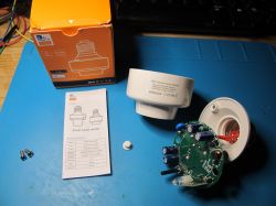
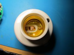
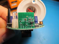
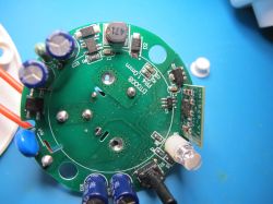
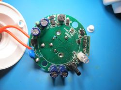
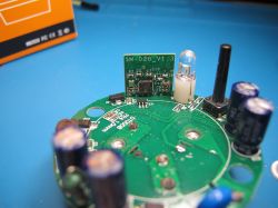
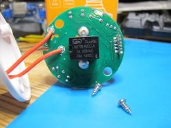
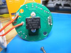
B:Sonoff_Devices_DIY_Tools-masterBouffaloLabDevCube-v1.9.0>ler.py flash.bin
Found 1 DTB candidate(s).

== DTB #1 @ file offset 0x001FC000, size 0x1BA2 (7074 bytes) ==
  Failed to parse DTB: 'int' object has no attribute 'decode'

######################## SUMMARY: Extracted DT properties ########################
No extractable /config_gpio or /gpio DT subtree found in any DTB candidate.


attached the flash.bin

thats the log from boufalou
[13:57:45.416] - ========= Interface is uart =========
[13:57:45.416] - com speed: 2000000
[13:57:45.416] - Eflash load helper file: B:Sonoff_Devices_DIY_Tools-masterBouffaloLabDevCube-v1.9.0chipsbl602eflash_loader/eflash_loader_40m.bin
[13:57:45.416] - ========= load eflash_loader.bin =========
[13:57:45.416] - Load eflash_loader.bin via uart
[13:57:45.417] - ========= image load =========
[13:57:45.698] - Not ack OK
[13:57:45.699] - FL
[13:57:45.701] - result: FL
[13:57:45.978] - tx rx and power off, press the machine!
[13:57:45.978] - cutoff time is 0.1
[13:57:46.088] - power on tx and rx
[13:57:46.899] - reset cnt: 0, reset hold: 0.005, shake hand delay: 0.1
[13:57:46.900] - clean buf
[13:57:46.909] - send sync
[13:57:47.129] - ack is 4f4b
[13:57:47.175] - shake hand success
[13:57:47.191] - get_boot_info
[13:57:47.193] - data read is b'010000000000000003000400b5923d0286241d00'
[13:57:47.193] - ========= chipid: 2486023d92b5 =========
[13:57:47.193] - last boot info: None
[13:57:47.193] - sign is 0 encrypt is 0
[13:57:47.193] - segcnt is 1
[13:57:47.200] - segdata_len is 38592
[13:57:47.284] - 4080/38592
[13:57:47.368] - 8160/38592
[13:57:47.452] - 12240/38592
[13:57:47.535] - 16320/38592
[13:57:47.619] - 20400/38592
[13:57:47.703] - 24480/38592
[13:57:47.789] - 28560/38592
[13:57:47.874] - 32640/38592
[13:57:47.957] - 36720/38592
[13:57:47.997] - 38592/38592
[13:57:47.999] - Run img
[13:57:48.106] - Load helper bin time cost(ms): 2688.489501953125
[13:57:48.213] - Flash load shake hand
[13:57:48.231] - default set DTR high
[13:57:48.337] - clean buf
[13:57:48.347] - send sync
[13:57:48.574] - ack is 4f4b
[13:57:48.620] - Read mac addr
[13:57:48.622] - macaddr: b5923d028624
[13:57:48.622] - flash set para
[13:57:48.623] - ========= flash read jedec ID =========
[13:57:48.624] - Read flash jedec ID
[13:57:48.624] - flash jedec id: c8401580
[13:57:48.624] - Finished
[13:57:48.631] - get flash size: 0x00200000
[13:57:48.631] - ========= flash read jedec ID =========
[13:57:48.633] - Read flash jedec ID
[13:57:48.633] - flash jedec id: c8401580
[13:57:48.633] - Finished