logo elektroda
logo elektroda
X
logo elektroda

[BL602] IoT relay series on BL602, SM-028_V1.3, KR0548-2CH-W, KR05-1CH

p.kaczmarek2 24648 39
ADVERTISEMENT
Treść została przetłumaczona polish » english Zobacz oryginalną wersję tematu
  • [BL602] IoT relay series on BL602, SM-028_V1.3, KR0548-2CH-W, KR05-1CH
    I put here a description of the pins of smart relays with the WiFi / Bluetooth BL602 Bouffalo Lab module. The basic module is the TROLINK SM-028_V1.3 BL602L20, it is used in the QIACHIP KR05-1CHKG-W relay and in the QIACHIP KR0548-2CH-W relay. Most likely, they are used by the entire series, i.e. the KR05-1CH, KR0548-1CH, KR0548-2CH and KR0548-4CH models. Without changing the firmware, they work with the eWeLink application, uploading OpenBeken allows you to free them from the cloud. These relays here are available to buy without a housing, it is the so-called. "DIY" version, they are additionally powered from USB - 5V.

    The materials collected here were sent to me by one of the US users on Github. I'm posting them here at his request. Thank you!

    SM-028_V1.3 BL602L20
    Here is the module itself - pins probably inspired by TYWE2S from ESP8266 (and also WB2S, CB2S and so on)
    [BL602] IoT relay series on BL602, SM-028_V1.3, KR0548-2CH-W, KR05-1CH
    LABEL GPIOs PIN
    L GPIO_1 2
    AND GPIO_4 5
    b GPIO_20 29
    g GPIO_14 22
    R GPIO_3 4
    22 GPIO_22 31
    17 GPIO_17 28
    c GPIO_21 thirty
    In GPIO_2 3

    The pins of the integrated circuit itself, QFN housing:
    [BL602] IoT relay series on BL602, SM-028_V1.3, KR0548-2CH-W, KR05-1CH
    The UART port used for logging (and for programming) here are the P16 (TX) and P7 (RX) signals, they are on the back of the module, loose. There is also a BT signal that allows you to start programming mode, as in my topic:
    https://www.elektroda.pl/rtvforum/topic3889041.html
    The log baud on this platform is 2000000.
    For comparison - TYWE2S:
    [BL602] IoT relay series on BL602, SM-028_V1.3, KR0548-2CH-W, KR05-1CH

    QIACHIP KR05-1CHKG-W (SM-028_V1.3 BL602L20)
    To buy on various Chinese portals, not always with the given model:
    [BL602] IoT relay series on BL602, SM-028_V1.3, KR0548-2CH-W, KR05-1CH
    [BL602] IoT relay series on BL602, SM-028_V1.3, KR0548-2CH-W, KR05-1CH
    Connection:
    [BL602] IoT relay series on BL602, SM-028_V1.3, KR0548-2CH-W, KR05-1CH
    Photo of what it looks like in reality, from the user:
    [BL602] IoT relay series on BL602, SM-028_V1.3, KR0548-2CH-W, KR05-1CH
    Roles of individual pins (for use with OpenBeken):
    Btn -> GPIO_14 (G)
    Rel -> GPIO_20 (B)
    WifiLED_n -> GPIO_22 (22)


    QIACHIP KR0548-2CH-W (SM-028_V1.3 BL602L20)
    There are even more results here, it's a bit easier to find this product under "KR0548-2CH-W". Even on the Qihip website:

    [BL602] IoT relay series on BL602, SM-028_V1.3, KR0548-2CH-W, KR05-1CH
    [BL602] IoT relay series on BL602, SM-028_V1.3, KR0548-2CH-W, KR05-1CH
    [BL602] IoT relay series on BL602, SM-028_V1.3, KR0548-2CH-W, KR05-1CH
    Other portal:
    [BL602] IoT relay series on BL602, SM-028_V1.3, KR0548-2CH-W, KR05-1CH
    [BL602] IoT relay series on BL602, SM-028_V1.3, KR0548-2CH-W, KR05-1CH
    [BL602] IoT relay series on BL602, SM-028_V1.3, KR0548-2CH-W, KR05-1CH
    [BL602] IoT relay series on BL602, SM-028_V1.3, KR0548-2CH-W, KR05-1CH
    [BL602] IoT relay series on BL602, SM-028_V1.3, KR0548-2CH-W, KR05-1CH
    Photo of what it looks like in reality, from the user:
    [BL602] IoT relay series on BL602, SM-028_V1.3, KR0548-2CH-W, KR05-1CH
    Roles of individual pins (for use with OpenBeken):
    Btn(1) -> GPIO_20 (B)
    Rel(1) -> GPIO_21 (C)
    Btn(2) -> GPIO_4 (A)
    Rel(2) -> GPIO_17 (17)
    WifiLED_n -> GPIO_14 (G)

    KR0548-4CH module
    Neither I nor the user had this module physically, but I will post its photos from sellers' offers anyway.
    [BL602] IoT relay series on BL602, SM-028_V1.3, KR0548-2CH-W, KR05-1CH
    [BL602] IoT relay series on BL602, SM-028_V1.3, KR0548-2CH-W, KR05-1CH
    Other seller:
    [BL602] IoT relay series on BL602, SM-028_V1.3, KR0548-2CH-W, KR05-1CH
    Module photos:
    [BL602] IoT relay series on BL602, SM-028_V1.3, KR0548-2CH-W, KR05-1CH [BL602] IoT relay series on BL602, SM-028_V1.3, KR0548-2CH-W, KR05-1CH [BL602] IoT relay series on BL602, SM-028_V1.3, KR0548-2CH-W, KR05-1CH [BL602] IoT relay series on BL602, SM-028_V1.3, KR0548-2CH-W, KR05-1CH [BL602] IoT relay series on BL602, SM-028_V1.3, KR0548-2CH-W, KR05-1CH [BL602] IoT relay series on BL602, SM-028_V1.3, KR0548-2CH-W, KR05-1CH [BL602] IoT relay series on BL602, SM-028_V1.3, KR0548-2CH-W, KR05-1CH [BL602] IoT relay series on BL602, SM-028_V1.3, KR0548-2CH-W, KR05-1CH
    Leads - to be completed. The module is quite cheap, maybe someone will be tempted to experiment?

    Summary
    Thanks to OpenBeken on Github for sharing information about the modules and for specifying their pins. It will definitely come in handy - OpenBeken supports the BL602 platform, so these devices can be freed from the cloud, and not only them - at the moment the BK7231T, BK7231N, BL602, XR809, T34, W800/W801 and W600/W601 platforms are supported.
    About OpenBeken for BL602:
    https://www.elektroda.pl/rtvforum/topic3889041.html
    Project repository:
    https://github.com/openshwprojects/OpenBK7231T_App
    Has anyone else encountered any devices on the BL602? Let me know, then we'll complete the topic.

    Cool? Ranking DIY
    Helpful post? Buy me a coffee.
    About Author
    p.kaczmarek2
    Moderator Smart Home
    Offline 
    p.kaczmarek2 wrote 11842 posts with rating 9938, helped 566 times. Been with us since 2014 year.
  • ADVERTISEMENT
  • #2 20361131
    rubik123
    Level 21  
    Can it be configured so that the relay turns on for 0.5s, e.g. to control the gate?
  • #3 20363205
    p.kaczmarek2
    Moderator Smart Home
    If you're asking about the original app, I'm not sure, although there were simple automations available.
    If you are asking about OpenBeken, yes, you can freely script it and the scripts are executed on the device itself, even without internet access.

    But overall I advise against BL602. It's better to go for proven solutions, i.e. ESP, and if you want something else, Tuya products on BK7231T or BK7231N are more often than BL602 and they are also better supported by OpenBeken.
    Helpful post? Buy me a coffee.
  • #4 20363218
    rubik123
    Level 21  
    Approx. I will keep that in mind when purchasing. Thank you.
  • #5 20364093
    michaeljuniper
    Level 2  
    Hi, I have a smart switch.
    [BL602] IoT relay series on BL602, SM-028_V1.3, KR0548-2CH-W, KR05-1CH

    As you can see it stated eWeLink compatible so I assumed (foolishly!) it had an ESP chip inside.

    It does not, but has a BL602L20 chip mounted on a SM-028_V1.3 BL602L20 module.

    [BL602] IoT relay series on BL602, SM-028_V1.3, KR0548-2CH-W, KR05-1CH

    I would like to replace the SM-028_V1.3 BL602L20 with an ESP based module (TYWE2S) that I can then flash with Tasmota.

    [BL602] IoT relay series on BL602, SM-028_V1.3, KR0548-2CH-W, KR05-1CH

    Given your knowledge of these modules, is it just a case of desoldering the SM-028_V1.3 BL602L20 module and replace it with the ESP module?
    Then flash with Tasmota.

    I have two switches so I shall try OpenBK7231T/OpenBeken on the other one and compare.
    Thanks in advance for you help.
  • #6 20364122
    p.kaczmarek2
    Moderator Smart Home
    Hello @michaeljuniper , I didn't check the datasheet now, but I did a XR809 to ESP8266 transplant in the past in this topic:
    https://www.elektroda.com/rtvforum/topic3816654.html
    In a nutshel, for that transplant, I:
    Quote:

    Unfortunately, the AP did not appear. I had to check each pin with a multimeter. My suspicions has confirmed. I had to add a 10k pull up resistor for EN and GPIO0 and a pull down resistor for GPIO15. In addition, I had to remove the diode from GPIO15 (unfortunately they just gave it there and this diode forced a high state on this pin and started ESP booting from an SD card ...).

    so you might have to add a one or two resistors in order for it to work. Consult datasheet of ESP8266 for required and forbidden pin states on startup. Pay attention to GPIO0 and EN and GPIO15. Also check your replacement module datasheet.

    Tell us if you manage to get it working, some photos of ready setup are also welcome. Good luck!

    You can also just try BL602 OBK port. For simple switch, it should be fully functional.

    EDIT:
    After a quick look at pinout, I think that a RST pin of ESP may be a problem? Is that particular pad used for something in your device?
    Helpful post? Buy me a coffee.
  • ADVERTISEMENT
  • #7 20364146
    michaeljuniper
    Level 2  
    Thank you for quick reply I will check out the pins which are used (rst pin) and I will update on my progress.
  • #8 20380238
    mikkojordman
    Level 1  
    Hi, I have flashed many ESPs but this is my first BL602. I dont get what pad does this mean?
    "BOOT from the module to the 10k resistor to the power supply"
    So, what pad/pin on BL602 / SM-028 is this "BOOT"?
  • #9 20380423
    p.kaczmarek2
    Moderator Smart Home
    Hello @mikkojordman . According to my knowledge, the BOOT pin on BL602 is D8.
    Instructions for handling the D8/GPIO8 pin on the DT-BL10 board.
    Helpful post? Buy me a coffee.
  • #10 20493237
    ipadbendavid
    Level 2  
    Hello Amazing work

    I would like to pair the Remote Control . What is the process ?
    Thank you
  • #11 20493250
    p.kaczmarek2
    Moderator Smart Home
    Hello, what kind of remote control, and which device?
    Helpful post? Buy me a coffee.
  • #12 20493470
    ipadbendavid
    Level 2  
    Hi
    I have successfully installed the OpenBeken. Its is working very well to control the 2 relays and 2 the buttons. But i don't how to add a Receiver for the Remote control / and to pair it.
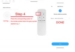
    Here the remote type. on the image below. on Weelink App , you can add a remote to control the Switch. It has 6 buttons (1, 2, 3, 4 all on and All off).

    Instructions for pairing an eWeLink remote with a device.

    Added after 8 [hours] 45 [minutes]:

    [17:00:19.067] - Starting bl602 now....
    ############################## system init ##################################
    Device Info:[Firmware Name:<FWSW-HSBL602-SWITCH-BL602L_v1.3.0>,Build Time:<20220412.141107.766>,Boot Reason:<BL_RST_POWER_OFF>]
    [17:00:19.175] - 鴟|>|   8>`虁鴟||   8`虁鴟
    [17:00:19.283] - ||  8 8`虁
    [17:00:19.392] - > 8 |  8 鄚鎩 
    [17:00:19.503] -  > |  8 鄚鎩   8 |  > >鄚苵 8
    [17:00:19.610] - cfg->led_status = 1
    Reading the dts file...
    And the GPIO config is :
    cfg->wifi_led = 14
    cfg->all_on_off = 200
    cfg->relay0 = 21
    cfg->relay1 = 17
    cfg->relay2 = 22
    cfg->relay3 = 2
    cfg->key0 = 20
    cfg->key1 = 4
    cfg->key2 = 1
    cfg->key3 = 3
    cfg->led_status = 1
  • ADVERTISEMENT
  • #13 20905068
    Jekob
    Level 2  
    >>20360406
    @p.kaczmarek2
    Good morning,
    I tried to use the ready-made OpenBL602_1.17.402.bin file from the repository and upload to the SM-028_V1.3 module soldered from some Chinese Mini switch. While the upload works, the module does not start properly, it resets all the time. Where to look for the cause? Tz is it possible to upload this ready-made bin or do you need to prepare your own.

    I attach the log from the serial port, the processor throws the same thing several times per second.
  • #14 20905126
    p.kaczmarek2
    Moderator Smart Home
    @Jekob at first glance I'm not sure what could be going wrong. The log looks like it's booting up old soft, but I could be wrong, I haven't physically interacted with a lot of devices on the BL602. In general, the very beginning of the log is quite interesting:
    
    RISC-V Core Feature:RV32-ACFIMX
    Build Version:      release_bl_iot_sdk_1.6.22-22-g1d4ff804-dirty
    Std Driver Version: 541807d
    PHY   Version:      a0_final-73-g62481a0
    RF    Version:      79cc6b9
    Build Date:         Jan 11 2024
    Build Time:         15:54:32
    Boot Reason:        BL_RST_POWER_OFF
    

    Boot reason to power off - could it be a power problem?
    Although I'm looking at it now, build date is January 11, 2024, so maybe something was uploaded....

    There was already a similar situation on the forum, and it turned out that someone was powering the module from some weak power supply or directly from the 3.3V pin from the USB to UART converter, causing the module to reset after a while.

    Can you show how you power the module, some pictures?

    A fairly efficient 3.3V source can be found on board the NodeMCU or Arduino UNO, for example.
    Helpful post? Buy me a coffee.
  • #15 20905200
    Jekob
    Level 2  
    @p.kaczmarek2 Wise is and nice to listen to
    I hooked up the Korad KD3005D, which indicates current draw varying between 55 and 65mA and the module seems to work, i.e. AP appeared
    Thank you very much.
  • ADVERTISEMENT
  • #16 20905218
    p.kaczmarek2
    Moderator Smart Home
    So that's it after all... in that case, I guess I'll add this problem to the FAQ, since it's not the first time I've seen it on the forum. I'll update https://github.com/openshwprojects/OpenBK7231T_App/blob/main/docs/faq.md right away
    Helpful post? Buy me a coffee.
  • #17 20909587
    stancecoke
    Level 3  
    Thank you for this great project. I use it for my E27 bulb socket relay
    https://www.ebay.de/itm/314264464569
    It has the same pinout as the QIACHIP KR05-1CHKG-W relay.
    Btn -> GPIO_14 (G)
    Rel -> GPIO_20 (B)
    WifiLED_n -> GPIO_22 (22)

    I use simple web query commands like "http://192.168.xxx.yyy/cm?cmnd=Power%20Off" so far, but I could'nt figure out, how to set a sleep timer. Is there a command to switch on the bulb for 20 minutes, then switch off automatically?

    [BL602] IoT relay series on BL602, SM-028_V1.3, KR0548-2CH-W, KR05-1CH

    regards
    stancecoke
  • #18 20909666
    p.kaczmarek2
    Moderator Smart Home
    Can you post here full OBK template?

    To switch of relay with a delay, you can use a repeating event with repeats count equal to one.
    Helpful post? Buy me a coffee.
  • #19 20909803
    stancecoke
    Level 3  
    this is my recent OBK template, but I've not filled any specific in there. It uses the SM-028 board.

    Code: JSON
    Log in, to see the code

    The device is sold at many places like ebay, amazon, aliexpress
    https://www.aliexpress.us/item/3256805856701661.html

    Can you post an example how to make a delay, using web query commands?

    regards
    stancecoke
  • #20 20909962
    p.kaczmarek2
    Moderator Smart Home
    The examples are already shown on the autoexecs samples page, but they are for platforms with LittleFS, so you need to modify them a bit:
    https://github.com/openshwprojects/OpenBK7231T_App/blob/main/docs/autoexecExamples.md
    But long story short:
    
    // command will turn off relay on CH1 after 10 seconds
    // addRepeatingEvent	[IntervalSeconds][RepeatsOr-1][CommandToRun]
    addRepeatingEvent 10 1 setChannel 1 0
    
    Helpful post? Buy me a coffee.
  • #21 20910270
    stancecoke
    Level 3  
    Thank you, but I can't manage to create the autoexec.bat file on the device. Both methods, drag an existing file and using the button "create file" fail. :-(
    I watched this tutorial: https://www.youtube.com/watch?v=kXi8S12tmC8
    With pressing "List Filesystem" nothing happens.

    regards
    stancecoke
  • #22 20910293
    p.kaczmarek2
    Moderator Smart Home
    LittleFS is not available on Bl602 yet. For BL602, you need to either stuff your commands in the short startup command or send them via HTTP at runtime.
    Helpful post? Buy me a coffee.
  • #23 20910410
    stancecoke
    Level 3  
    OK, I understand. Which set of commands is available for the BL602 via http? Sorry for this newbie questions, I'm normally dealing with C on STM32 mikroprocessors.

    regards
    stancecoke
  • #24 20910460
    p.kaczmarek2
    Moderator Smart Home
    Most of the commands from our docs should be available on BL602 already. Only some of the drivers are missing from BL602.
    https://github.com/openshwprojects/OpenBK7231T_App/blob/main/docs/commands.md
    Helpful post? Buy me a coffee.
  • #25 20910504
    stancecoke
    Level 3  
    OK, I'll try. The mechanical button for manually switch the relay is not reachable, if the E27 relay device is installed. What is the easiest way to switch via a smart button? I don't want to use the mobile phone.
    There are several door bell buttons or emergency buttons available, can they send the web query directly, or do you have to use a server like a raspberry
  • #26 20910538
    p.kaczmarek2
    Moderator Smart Home
    You can either use HTTP GET commands, syntax is like in the Tasmota, or Tasmota Device Groups:


    If you don't want to use Tasmota Device Groups, look into the SendGet command.
    
    // when channel 1 becomes 0, send OFF
    addChangeHandler Channel1 == 0 SendGet http://192.168.0.112/cm?cmnd=Power0%20OFF
    // when channel 1 becomes 1, send ON
    addChangeHandler Channel1 == 1 SendGet http://192.168.0.112/cm?cmnd=Power0%20ON
    
    Helpful post? Buy me a coffee.
  • #27 20910617
    stancecoke
    Level 3  
    Is there a battery driven button that uses WiFi? Or are there only 433MHz or BLE Buttons?
    Can Open Beken receive 433MHz signals?

    Update:
    with this python command, the lamp switches on for 20 minutes (1200 s), thank you for your help!

    r = requests.get('http://192.168.xxx.yyy/cm?cmnd=backlog%20Power%20on;%20addRepeatingEvent%201200%201%20setChannel%200%200',headers={'Accept': 'application/json'})


    regards
    stancecoke
  • #28 20987133
    divadiow
    Level 34  
    I just got round to trying the KR0548-1CH-W I bought a while ago.

    Boot log from BL602.

    [10:11:46.743] - Starting bl602 now....
    ############################## system init ##################################
    Device Info:[Firmware Name:<FWSW-HSBL602-SWITCH-BL602L_v1.3.3>,Build Time:<2022061
    [10:11:46.745] - 4.144049.148>,Boot Reason:<BL_RST_POWER_OFF>]
    [10:11:47.338] - cfg->led_status = 0
    Reading the dts file...
    And the GPIO config is :
    cfg->wifi_led = 22
    cfg->all_on_off = 200
    cfg->relay0 = 20
    c
    [10:11:47.340] - fg->relay1 = 200
    cfg->relay2 = 200
    cfg->relay3 = 200
    cfg->key0 = 14
    cfg->key1 = 200
    cfg->key2 = 200
    cfg->key3 = 200
    cfg.led_status = 0
    cfg->led_status = 0
    Reading the dts file...
    And the GPIO config is :
    cfg->wifi_led = 22
    cfg->all_on_off = 200
    cfg->relay0 = 20
    cfg->relay1 = 200
    cfg->relay2 = 200
    cfg->relay3 = 200
    cfg->key0 = 14
    cfg->key1 = 200
    cfg->key2 = 200
    cfg->key3 = 200
    cfg.led_status = 0


    flashID info from Bouffalo Lab Dev Cube 1.8.9

    [10:06:47.077] - Version: eflash_loader_v2.5.0
    [10:06:47.078] - Program Start
    [10:06:47.078] - ========= eflash loader cmd arguments =========
    [10:06:47.078] - Config file: C:\Users\xxx\BouffaloLabDevCube-v1.8.9\chips\bl602\eflash_loader\eflash_loader_cfg.ini
    [10:06:47.082] - serial port is COM9
    [10:06:47.083] - cpu_reset=False
    [10:06:47.084] - chiptype: bl602
    [10:06:47.085] - ========= Interface is uart =========
    [10:06:47.085] - com speed: 2000000
    [10:06:47.086] - Eflash load helper file: C:\Users\xxx\BouffaloLabDevCube-v1.8.9\chips\bl602\eflash_loader/eflash_loader_40m.bin
    [10:06:47.086] - ========= load eflash_loader.bin =========
    [10:06:47.086] - Load eflash_loader.bin via uart
    [10:06:47.086] - ========= image load =========
    [10:06:47.334] - Not ack OK
    [10:06:47.335] - FL
    [10:06:47.335] - result: FL
    [10:06:47.615] - tx rx and power off, press the machine!
    [10:06:47.616] - cutoff time is 0.1
    [10:06:47.724] - power on tx and rx
    [10:06:48.542] - reset cnt: 0, reset hold: 0.005, shake hand delay: 0.1
    [10:06:48.543] - clean buf
    [10:06:48.546] - send sync
    [10:06:48.758] - ack is 4f4b
    [10:06:48.805] - shake hand success
    [10:06:48.821] - get_boot_info
    [10:06:48.832] - data read is b'0100000000000000030000006382be4cb97c1700'
    [10:06:48.832] - ========= chipid: 7cb94cbe8263 =========
    [10:06:48.832] - last boot info: None
    [10:06:48.833] - sign is 0 encrypt is 0
    [10:06:48.835] - segcnt is 1
    [10:06:48.863] - segdata_len is 38592
    [10:06:48.959] - 4080/38592
    [10:06:49.054] - 8160/38592
    [10:06:49.151] - 12240/38592
    [10:06:49.247] - 16320/38592
    [10:06:49.343] - 20400/38592
    [10:06:49.439] - 24480/38592
    [10:06:49.534] - 28560/38592
    [10:06:49.630] - 32640/38592
    [10:06:49.726] - 36720/38592
    [10:06:49.774] - 38592/38592
    [10:06:49.791] - Run img
    [10:06:49.907] - Load helper bin time cost(ms): 2821.169921875
    [10:06:50.016] - Flash load shake hand
    [10:06:50.029] - default set DTR high
    [10:06:50.141] - clean buf
    [10:06:50.144] - send sync
    [10:06:50.373] - ack is 4f4b
    [10:06:50.420] - Read mac addr
    [10:06:50.431] - macaddr: 6382be4cb97c
    [10:06:50.432] - flash set para
    [10:06:50.432] - ========= flash read jedec ID =========
    [10:06:50.446] - Read flash jedec ID
    [10:06:50.447] - flash jedec id: ef401580
    [10:06:50.447] - Finished
    [10:06:50.455] - get flash size: 0x00200000
    [10:06:50.456] - ========= flash read jedec ID =========
    [10:06:50.463] - Read flash jedec ID
    [10:06:50.464] - flash jedec id: ef401580
    [10:06:50.464] - Finished


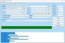
    and finally quite a successful flash using solely the latest Dev Cube, latest partition and boot2 files (!). I dispensed with the breadboard and connected power/ground using wagos. I also bumped the PSU up to 3.5v.

    flash was successful using a Prolific 2303 and 100000 baud in BLDC. I also made sure the device was pairing (with EweLink app) (as a desoldered module powered externally) and not boot looping BEFORE I flashed OBK. Then after flashing OBK the AP appeared without issue.

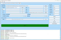
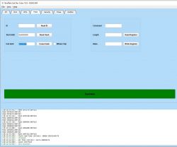
    Bouffalo Lab Dev Cube 1.8.9 interface with loaded firmware

    whole 2mb flash was dumped, attached

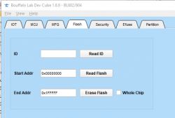
    Bouffalo Lab Dev Cube interface with Flash tab

    to complete the template @stancecoke posted https://www.elektroda.com/rtvforum/topic3945435.html#20909803
    I went with wifi (not _n) so the behaviour is that the blue LED is flashing on wifi connecting then off when connected. The red LED (not controllable) comes on with the relay in one of the positions anyway.

    Code: JSON
    Log in, to see the code


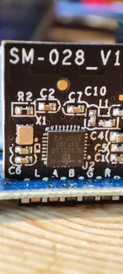
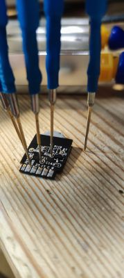
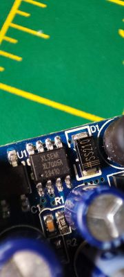
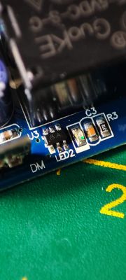
    various pics

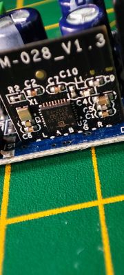
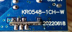
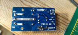
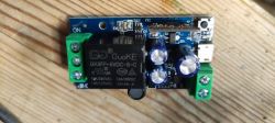
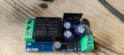
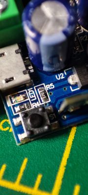
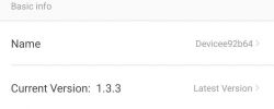
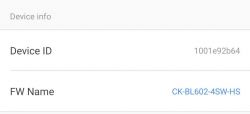
    Close-up of a circuit board labeled SM-028_V1.3 with electronic components. Image of an electronic circuit board KR0548-1CH-W with visible solder connections and the number 20220618. KR0548-1CH-W PCB with labeled connectors and traces. Printed circuit board with electronic components and a relay. Qiachip relay module with electronic components. Close-up of a circuit board labeled SM-028_V1 with integrated circuits and other electronic components. Printed circuit board with connected test probes on a wooden surface. Close-up of electronic components on a circuit board, including an XLSEMI XL7005A chip and an SS210 diode. Close-up of electronic components on a circuit board. Close-up of a circuit board with electronic components. Screen snippet displaying the device software version information. Screenshot showing device information including Device ID and FW Name.
  • #30 20993476
    divadiow
    Level 34  
    I'm on a roll with the BL602s now. Today I did the 2-channel version of the above, same as the OP - KR0548-2CH-W.

    Same process as my previous post but this time the SM-028_v1.3 was happy at 3.4v. no boot loops at any point. dump of factory flash and flash to OBK at first attempt.

    Here is original boot log

    Code: Text
    Log in, to see the code


    Here is flash ID get using BLDC 1.8.9

    Code: Text
    Log in, to see the code


    Screenshot of BouffaloLab Dev Cube showing flash success.

    here is visual flash of OBK success then the text output of flash log

    Bouffalo Lab Dev Cube 1.8.9 interface during BL602 programming.
    Code: Text
    Log in, to see the code


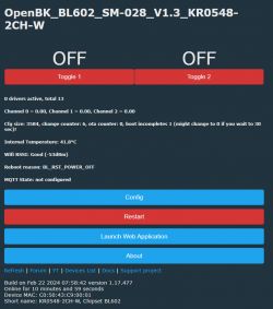
    and finally the log out of OBK itself after flash

    Code: Text
    Log in, to see the code


    Control panel of OpenBK for dual-channel device with BL602 chipset.

    pin config used from existing device list entry

    Code: Text
    Log in, to see the code


    This was flashed at 2000000 baud and with an FTDI USB TTL

Topic summary

The discussion revolves around the BL602-based IoT relay series, specifically the TROLINK SM-028_V1.3 module used in QIACHIP relay models KR05-1CH, KR0548-1CH, KR0548-2CH, and KR0548-4CH. Users inquire about configuring the relays for specific tasks, such as controlling a gate, and the compatibility of the BL602 with various applications like eWeLink and OpenBeken. Concerns are raised regarding the reliability of the BL602 compared to ESP-based solutions, with suggestions to consider Tuya products on BK7231T or BK7231N for better support. Users share experiences with flashing firmware, troubleshooting boot issues, and integrating remote controls. The conversation also touches on GPIO configurations and the use of HTTP commands for relay control.
Summary generated by the language model.
ADVERTISEMENT