logo elektroda
logo elektroda
X
logo elektroda

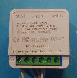
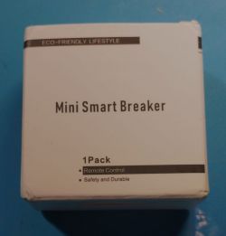
[SM-02/BL602L20] Mini Smart Breaker RMW002 Flashing OpenBL602 on BL602L20 Flash Like Esphome

climberfather 14580 40
ADVERTISEMENT
  • About Author
    climberfather
    Level 1  
    Offline 
    climberfather wrote 1 posts with rating 6, helped 1 times. Been with us since 2023 year.
  • ADVERTISEMENT
  • #2 20783995
    p.kaczmarek2
    Moderator Smart Home
    It's nice to see another BL602 device! It seems that supporting that platform was worth it.

    Thanks for the template, I will add it to our devices list.
    Helpful post? Buy me a coffee.
  • ADVERTISEMENT
  • #3 20795350
    stefan_73
    Level 3  
    Got the same device from Aliexpress. Did a reverse engineering of the traces. In my version of the RMW002 the config is similar but not identical to the config described above.
    GPIO_3 = TglChanOnTgl
    GPIO_20 = Button
    GPIO_14 = LED_n
    GPIO_21 = Relais
    With TglChanOnTgl also the external switch works (S1/S2).
    Screenshot of OpenBL602 device pin configuration.

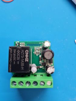
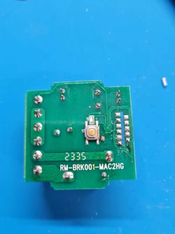
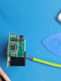
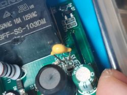
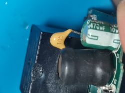
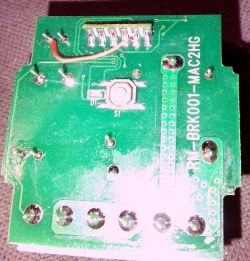
    Here are some photos from the internals. SM-28 Board removed for better visibility of traces.
    Electronic module with components on a blue background. Close-up of a circuit board labeled RM-BRK001-MAC2HG on a blue background. Close-up of a SM-28 V1.3 circuit board with visible traces and components on a blue background.
  • #4 20795353
    p.kaczmarek2
    Moderator Smart Home
    Hello, can you post a GPIO template from the Web App?
    Helpful post? Buy me a coffee.
  • #5 20795450
    stefan_73
    Level 3  
    Sure, here you go.

    {
      "vendor": "Noname",
      "bDetailed": "0",
      "name": "Mini Smart Switch",
      "model": "RMW002",
      "chip": "BL602",
      "board": "SM-028",
      "flags": "1024",
      "keywords": [
        "TODO",
        "TODO",
        "TODO"
      ],
      "pins": {
        "3": "TglChanOnTgl;1",
        "14": "LED_n;1",
        "20": "Btn;1",
        "21": "Rel;1"
      },
      "command": "",
      "image": "https://obrazki.elektroda.pl/5649141700_1698005842.jpg",
      "wiki": "https://www.elektroda.com/rtvforum/viewtopic.php?p=20795450#20795450"
    }
  • #6 20800210
    array81
    Level 6  
    I'd like to buy one. Is there a guide on how to flash the firmware? Do you need to access the card? How do you open the box since the plastic seems welded?
  • #7 20800216
    stefan_73
    Level 3  
    Yes, you have to open the device which is rather simple. It is not welded just clipped. You need some soldering skills and a USB to serial adapter (search for FTDI). You can find several guides on how to flash the SM_28-V1.3 Module that is in this device.
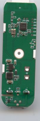
    The problem for beginners will be that you need to unsolder the SM_28 from the main PCB (see photos). This is needed as you need to access soldering points on the rear side of the module. You find soldering point for 3.3V,Gnd,RX,TX and Boot on this side. Those points are labeled.
  • #8 20800220
    p.kaczmarek2
    Moderator Smart Home
    @array81 do you want to buy this specific BL602 device, or a generic smart relay? You can also get a BK7231 version very often.

    See our flashing guides: https://www.youtube.com/@elektrodacom
    Helpful post? Buy me a coffee.
  • #9 20800236
    array81
    Level 6  
    On image see only RMW002. I don't know the chipset but if I understand BL602 and BK7231 works. But how flash the firmware, I Need open It?
  • ADVERTISEMENT
  • #10 20800352
    p.kaczmarek2
    Moderator Smart Home
    It is very easy to open such devices. They are not glued. There are no screws.
    Helpful post? Buy me a coffee.
  • #11 20806790
    hard3d
    Level 7  
    Good afternoon! Is there any software protection against rattling?
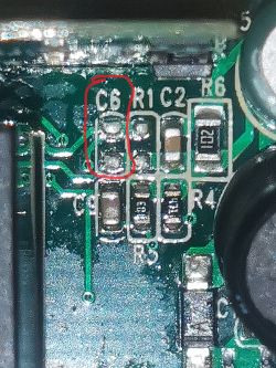
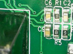
    I have 2 devices and one of them is missing a C6 capacitor. And when I activate the 3 pin, the relay starts clicking.

    Close-up of a circuit board with a missing capacitor C6. Close-up of a circuit board with a missing C6 capacitor marked.
  • #12 20806830
    p.kaczmarek2
    Moderator Smart Home
    What do you mean by rattling? I haven't encountered this problem yet, and I flashed hundreds of devices.
    Helpful post? Buy me a coffee.
  • #13 20807168
    ildarnizamutdinov
    Level 1  
    >>20806790

    I also had no C6 and there was a rattle of contacts when I turned on pin 3 in togle mode. Soldered C6 = 100nF and resistor R1 = 100k and the rattle disappeared
  • #14 20807261
    hard3d
    Level 7  
    I only soldered the capacitor. SMD was not available, soldered what was.

    Close-up of a circuit board with a soldered capacitor and components. Close-up of a circuit board with a manually soldered capacitor.
  • #15 20807303
    p.kaczmarek2
    Moderator Smart Home
    I'd personally shorten the leads of that capacitor before soldering, shortening leads reduces the noise
    Helpful post? Buy me a coffee.
  • ADVERTISEMENT
  • #16 20819709
    array81
    Level 6  
    Hi,
    I received my RMW002 today and was able to open it without damaging it. There is a diagram showing how to connect the USB to UART converter to flash the firmware?

    regards
  • #17 20819870
    p.kaczmarek2
    Moderator Smart Home
    We have the following BL602 video guides:


    Helpful post? Buy me a coffee.
  • #18 20820951
    array81
    Level 6  
    Last night, I opened the device, unsoldered SM_28, loaded the firmware, resoldered SM_28, soldered the resistor and the capacitor (without actually the relay it seemed crazy), I configured the firmware, connected it to my Home Assistant and everything worked correctly. This morning I decide to install it in my system and nothing works. The device does not turn on at all. When connected to the mains the LED does not light up. Only once did I see it cast a very dim light for a very short time. Crazy stuff.
  • #19 20842926
    adamspaiva
    Level 2  
    I have this same model, but I couldn't get the external switch to work. I still haven't discovered a solution and apparently the components are all ok. The impressive thing is when I use a diode scale multimeter (not advisable) pins S1 and S2 normally function as an external switch)
  • #20 20843012
    p.kaczmarek2
    Moderator Smart Home
    @adamspaiva can you provide more information? Was it working with Tuya firmware?
    Helpful post? Buy me a coffee.
  • #21 20843733
    adamspaiva
    Level 2  
    I have no idea, this is my first smart switch device, so I'm reading your project on github to learn something. I started measuring the board and the next step is to buy an ftdi. I can send some photos of the circuit and ics if it helps.
  • #22 20843805
    p.kaczmarek2
    Moderator Smart Home
    Have you set the correct GPIO role for the switch sensor? The "TglChannelOnToggle"?
    Helpful post? Buy me a coffee.
  • #23 20843957
    stefan_73
    Level 3  
    It seems we cannot rely on the RWM002 marking. I now received one over Aliexpress, which contains a LN882HK chip. So it is currently not supported by OpenBeken or other firmware alternatives. From the outside and all text on the case it looks exactly like the photo in post 1.
  • #24 20852925
    array81
    Level 6  
    Is there a way to set the relay to be closed and not open at startup?
  • #25 20853244
    p.kaczmarek2
    Moderator Smart Home
    This can be configured in the Startup menu. Alternatively, you can just script anything you want in the autoexec.bat, even with the delay, etc...
    Helpful post? Buy me a coffee.
  • #26 20855410
    LuidgiVampa
    Level 5  
    Разобрал rmw002 (bl602l20) С кондёра С5 на землю висит сопля.
    I disassembled the rmw002 (bl602l20) There is a wire hanging from the C5 to GND.
    Close-up of a printed circuit board with soldered wires.

    I tested this relay for a couple of days. What can I say. The device did not inspire confidence in me. A phantom switching on and off occurs every hour. It cannot be used in serious projects. May be I have a bad relay module.
  • #27 20859608
    LuidgiVampa
    Level 5  
    Ложные срабатывания RWM002 решение проблемы (Solution - RWM002 phantom switching)
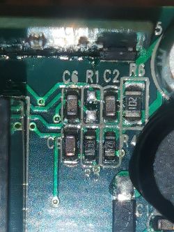
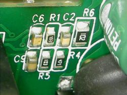
    To solve the problem, you need to solder the elements onto plates R1 and C6. R1- 10 kOhm, C6- 0.1 mF. After soldering these smd elements on the board, switching problems should stop.

    My revision.
    Circuit board with marked components R1, C6, R6, and others.

    Close-up of a circuit board with markings C6, R1, C2, and SMD components.

    P.S.
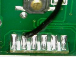
    I completely forgot to write! If your wire is red. Be sure to change it to a black wire. Otherwise the rocket won't fly! ))))))
    Close-up of a PCB with a soldered black wire.
  • #28 20860071
    p.kaczmarek2
    Moderator Smart Home
    Interesting, how those elements caused phantom switching?

    PS: Remember to use PowerSave in OpenBeken in those devices. This reduces stress on their low quality power supplies.
    Helpful post? Buy me a coffee.
  • #29 20860356
    LuidgiVampa
    Level 5  
    I can’t say for sure here. I found the solution on the Internet. And it's working. Unfortunately, the person who was able to overcome this illness left only the denominations of the elements. And no more information. I quickly rang the tester. These elements are connected to dry contact S2, PAD_gpio3 (if I'm not mistaken). They are not pulled to the ground and do not participate in the formation of power supply.
    I bought this relay for review. On sale for 2$. The price didn’t scare me, I guessed there would be problems. The product has more than 200 bad reviews with this problem. There are still many complaints that S1-S2 does not work.
  • #30 20866048
    nunomam
    Level 1  
    Hi

    I've bought a similar item.
    Is there any way to configure P3 as TglChanOnTgl - Pull Up?

    If I configure P3 (external switch) as dInput, it works, but the external button doesn't have the toggle mode.

    If I configure P3 as TglChanOnTgl, the relay is always randomly switching on and off.

    Thanks.

Topic summary

The discussion revolves around the Mini Smart Breaker RMW002, which features a BL602L20 microcontroller and is flashed with OpenBL602 firmware. Users share their experiences with the device, including configuration details, GPIO pin assignments, and issues related to phantom switching and firmware flashing. Some users report successful flashing and integration with Home Assistant, while others encounter problems such as boot loops and external switch functionality. Solutions are proposed, including soldering specific components to mitigate issues. The community also discusses the ease of opening the device and the necessity of soldering skills for firmware updates.
Summary generated by the language model.
ADVERTISEMENT