Hi, my first post  .
.
I have such a simple lamp in my child's room

I wanted to solve 2 problems:
1. the lamp was shining too brightly, my son had difficulty falling asleep.
2. son never wants to go to sleep, so he won't let the light go out. In another lamp I have a bulb hooked up to Home Assistant, where I did a simple automation to slowly dim until it turns off. To this the son does not protest I thought I would add ESP to the wolf light and do the same.
On closer inspection of the willy lamp, it turns out to be a very simple design, almost DIY. A piece of cut plywood, a 3D printed plastic housing on the back, a piece of LED tape inside, all powered by a 5V power supply (Philips, I see online that this particular model comes with cordless phones) with a switch on the cord.
My idea was to put the smallest ESP possible into the case, in this case I'm using ESP01. Plus a piece of code in ESPHome to have integration with Home Assistant straight away. I also wanted to make sure that my integration into the light was not visible from the outside and that the switch on the cable still worked.
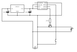
The result was this arrangement:
 .
.
On the board it works .
.
Assembly time has come and here I have a request for feedback. Have I messed up anything here? I am not an electronics engineer, so all my knowledge is based on posts on the internet.
For this I have 2 questions:
1. I have the switch connected to GPIO2, so ESP01 only turns on in one state, if the switch is in the other state, ESP goes into flashing mode. I've dug all over the internet but still don't know how to make it better.
2. I've read that LM1117 is not the best solution, but I don't know what better to use here. In general the whole power supply is still in front of me, so maybe it can be done better?
I have such a simple lamp in my child's room

I wanted to solve 2 problems:
1. the lamp was shining too brightly, my son had difficulty falling asleep.
2. son never wants to go to sleep, so he won't let the light go out. In another lamp I have a bulb hooked up to Home Assistant, where I did a simple automation to slowly dim until it turns off. To this the son does not protest
On closer inspection of the willy lamp, it turns out to be a very simple design, almost DIY. A piece of cut plywood, a 3D printed plastic housing on the back, a piece of LED tape inside, all powered by a 5V power supply (Philips, I see online that this particular model comes with cordless phones) with a switch on the cord.
My idea was to put the smallest ESP possible into the case, in this case I'm using ESP01. Plus a piece of code in ESPHome to have integration with Home Assistant straight away. I also wanted to make sure that my integration into the light was not visible from the outside and that the switch on the cable still worked.
The result was this arrangement:
 .
.
On the board it works
Assembly time has come and here I have a request for feedback. Have I messed up anything here? I am not an electronics engineer, so all my knowledge is based on posts on the internet.
For this I have 2 questions:
1. I have the switch connected to GPIO2, so ESP01 only turns on in one state, if the switch is in the other state, ESP goes into flashing mode. I've dug all over the internet but still don't know how to make it better.
2. I've read that LM1117 is not the best solution, but I don't know what better to use here. In general the whole power supply is still in front of me, so maybe it can be done better?


