logo elektroda
logo elektroda
X
logo elektroda

[Solved] ESP 07S Lighting 2 channel - Physical and virtual push button control

mmaker 1815 31
ADVERTISEMENT
Treść zostaÅ‚a przetÅ‚umaczona polish » english Zobacz oryginalnÄ… wersjÄ™ tematu
  • #1 18090833
    mmaker
    Level 19  
    Hi. I have started to get interested in low-cost home automation based on ESP (because intelligence cannot be called that) in total a little bit out of compulsion and in connection with this I am tormented by one topic. The combination of control via WiFi and from a physical switch on the wall, similar to a normal automation installation where we have a KNX bus to each product, but in my case - all in Blynk. I have seen somewhere a project where someone made a back box module with wifi control and from a physical button but there the voltages on the button were low, in any case not 230V. I don't want to ruin the installation and I would prefer that when I press a (bell) button on the wall, the chosen light in the living room is switched on and that the status is refreshed in the Blynek (there can be a separate icon) and at the same time I can switch the light off or on from the phone app. From the physical switch on the wall, I already have wires led to the false ceiling where I have about 12cm of space, in addition there is a 230V constant power supply (here I thought I might have such ideas in the future :) ). I would need to use e.g. an optotransistor to read the state of the button, whether it has been pressed and change the state on the ESP output. Do you know of any examples of such solutions?
  • ADVERTISEMENT
  • Helpful post
    #2 18090932
    khoam
    Level 42  
    mmaker wrote:
    I would need to use e.g. an optotransistor to read the state of the button, whether it has been pressed and change the state on the ESP output.
    .
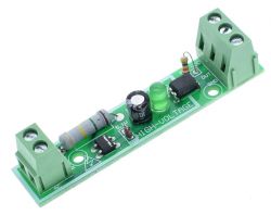
    Detection of 220V can be done as follows (ZC is shorted):

    ESP 07S Lighting 2 channel - Physical and virtual push button control .

    Or buy a module on ali for less than $2 (I use such):

    ESP 07S Lighting 2 channel - Physical and virtual push button control .

    EDIT: the above module can be powered from 3V3
  • ADVERTISEMENT
  • #3 18094281
    mmaker
    Level 19  
    Hello and thank you for the schematic, I was thinking of something similar, I can handle that, but the programming issue is bothering me. I'm programming the Atmega in C on a daily basis, and here I'm wondering if I'm going to have to do anything extra in the ESP to get it to work. I would prefer not to use additional widgets in the form of LEDs in the Blynk.... It would be nice if when clicking a button on the wall the status of the button on the phone would change.... Well nothing, apparently I'm in for a battle with C++ :D .
  • #4 18094288
    khoam
    Level 42  
    mmaker wrote:
    and here's where I wonder if I'll have to tinker with something extra in the ESP to make it want to work for me
    .
    Not necessarily: ESPEasy , Tasmota , ESPurna and probably a few more finished firmware would be found.
  • ADVERTISEMENT
  • #5 18096180
    mmaker
    Level 19  
    At the moment I have the NodeMCU uploaded and have tested with the LED connected via a resistor to the GPIO and it turns the LED on and off nicely. When I complete the schematic I'll ask you to check if it's ok.

    Added after 10 [hours] 18 [minutes]: .

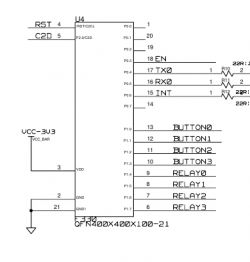
    I am attaching the schematic of the device, please check if it is ok
    ESP 07S Lighting 2 channel - Physical and virtual push button control
  • #6 18097676
    Slawek K.
    Level 35  
    The switches on the wall close the 230V circuit ? How are you going to connect your circuit under the switch ? I am referring to SL3 or SL4 in the diagram.

    Greetings
  • #7 18097748
    mmaker
    Level 19  
    A switch on the wall closes the 230V circuit, at the moment a normal double switch is fitted but will be replaced with a double 'bell' switch. I intend to connect the switches under SL3 and SL4.
  • #8 18097789
    Slawek K.
    Level 35  
    Can you draw a piece of the schematic diagram of how you will connect this considering the 230V mains?
    The signal diode of the relay should not be in series with the gate resistor but after the transistor, i.e. with the current limiting resistor between 3.3V and the collector of the transistor or between 12V and the collector of the optoisolator.

    Regards
  • #9 18097874
    mmaker
    Level 19  
    Slawek K. wrote:
    Can you draw a piece of a schematic diagram of how you will connect this considering the 230V network ?
    Do you mean the whole controller or just the part that detects when the switch is pressed?
  • #10 18097890
    Slawek K.
    Level 35  
    I am referring to the way the switch is connected and the circuit connection at the SLx location.
    If the switch is the location of a standard installation for switching lights, then there is a broken circuit through the switch at the switch, and that is the location we are talking about, unless I have misunderstood your concept.
  • #11 18097915
    mmaker
    Level 19  
    This is exactly how it is supposed to be, i.e. the switch will short-circuit the 230V circuit.
  • #12 18097928
    Slawek K.
    Level 35  
    And your circuit will be connected in what way to the switch ?
  • #13 18097936
    khoam
    Level 42  
    You are loading GPIO12 and GPIO13 with quite a bit of current. I figure it could be over 10 mA. Of course, a lot depends on the led used, but note that the max current for a single ESP8266 pin is 12 mA.
  • #14 18098062
    mmaker
    Level 19  
    As far as terminals SL3 and SL4 are concerned, I intend to connect the wires which now go to the lighting, i.e. for example under pin 1 of terminal SL3 I connect the neutral wire and under pin 2 the phase wire from the switch. In simpler words I disconnect the wires from the light source and connect them in place of the SL3 terminals and similarly the second circuit under SL4 😉

    I will move the LED on the coil side of the relay if it is to be safer ;) .
  • #15 18098325
    Slawek K.
    Level 35  
    That is, a current will flow through the bridge from the sensor equal to the load of the bulb, I assume you have used the correct one. However, I am intrigued that you want to replace the switch with a momentary (bell) switch, why ?

    Best regards
  • #16 18098810
    mmaker
    Level 19  
    Slawek K. wrote:
    That is, a current equal to the load on the bulb will flow through the bridge from the sensor
    .
    A small current will flow through the bridge (voltage drop across the resistor and the LED of the optotransistor after the Graetz bridge) and only when the button on the wall is pressed (the moment the circuit is closed) - this is to serve as a key-press sensor for the ESP.

    Slawek K. wrote:
    But I am intrigued that you want to replace the switch with a momentary (bell) switch, why ?
    .
    My idea here is that every time you press a key on the wall, the relays on the board should alternately switch one of the 2 lighting circuits on and off (the switch should be double = 2 circuits). In other words, pressing the key (mains voltage appearing on the SL3) should trigger the relay and switch on the first circuit. The next key press should switch the circuit off and so on over and over again.
  • #17 18098832
    Slawek K.
    Level 35  
    It is a pity that there is no diagram of the connection of the 230V circuits to the switch and relays and the connection of the detection system, because the discussion is quite virtual.
    For the moment I am therefore switching off.

    Best regards
  • #18 18099069
    mmaker
    Level 19  
    In simple terms, it should look like this:
    ESP 07S Lighting 2 channel - Physical and virtual push button control .
  • #19 18099080
    Slawek K.
    Level 35  
    Thank you, now everything is clear.
    My suggestion, you don't need a circuit with a bridge and an opto-isolator, it's enough to connect the switch directly to GPIO and GND, without the 230V network, because the lighting circuit is switched on by a relay anyway. And you have total galvanic isolation of the control circuit from the 230AC mains.
    The second thing to think about is to use an optotriac and a triac instead of an optoisolator and a relay ;) .

    Greetings
  • #20 18099088
    mmaker
    Level 19  
    Slawek K. wrote:
    My suggestion, the circuit with the bridge and optoisolator is unnecessary, the connector is enough to connect directly to GPIO and GND
    .
    In the first post I wrote why I don't want to do it that way :) Above the false ceiling I have room to insert the controller in plug & play mode, i.e. I connect and it works, without modifying the existing installation.
  • #21 18099096
    Slawek K.
    Level 35  
    Ok, I see, that makes sense ;) .
    I have edited the post in the meantime, have another look please at the relay issue.

    Greetings
  • ADVERTISEMENT
  • #22 18099139
    mmaker
    Level 19  
    With the optotriac and triac as an actuator, it's an interesting option in terms of reducing the size of the PCB itself, for now I'm thinking if I can manage to program it in the Arduino IDE and the relays will stay at least on this prototype.
  • #23 18105228
    mmaker
    Level 19  
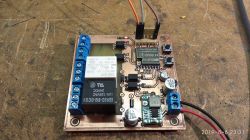
    Hello after a break :) The board is ready, the ESP programmed, it already works as I wanted it to, and this is how it looks:

    ESP 07S Lighting 2 channel - Physical and virtual push button control .

    Initially in the schematic I inserted a 3.3V LDO stabiliser, but quickly decided that this was pointless and planted a small inverter set to 3.3V in its place. Current draw from the power supply with the WIFI connected and both relays on is less than 100mA at 12V. I also added a small LED flashing every 500ms to check if the ESP has accidentally failed. I will soon mount in the target location and test :) .
  • #24 18105229
    khoam
    Level 42  
    Just out of curiosity, I'd like to ask what kind of antenna you connect to the ESP-07S?

    mmaker wrote:
    I also added a small LED flashing every 500ms to check if the ESP has accidentally failed.
    .
    heartbeat - I always do this too :) .
  • #25 18105278
    mmaker
    Level 19  
    I have a lot of U.FL pigtails for RPSMA and also a few 3dBi antennas will be found and on such a set it should work out ;) If it works out then I will act on it ;) .

    Update:
    I've made a small fuckup in the form of an "adapter" for the LED into which I push a 1mm plastic fibre optic (multimode) and the other end through a hole in the plasterboard next to the plafond ;) this way I can see if the module is working 😀

    As for the wifi antenna I used the one from my laptop that sits behind the matrix
  • #26 18143706
    krzbor
    Level 27  
    If you have access to a push-button cable and a 230 V power supply, plus 12 cm of space, then a sonoff dual is optimal. No need to worry about ESP, power supply, relays - everything is there! Most importantly - you can bring out the UART lines on the goldpins and program the circuit with your own software. There are also a couple of ports on the pins where you can attach physical buttons. Recently I've found that there's no point in building my own ESP-based actuators - it's better and cheaper to buy a sonoff and upload my own software.
  • #27 18143737
    mmaker
    Level 19  
    Hello
    krzbor wrote:
    If you have access to a push-button cable and a 230 volt power supply, plus 12 cm of space then a sonoff dual is optimal.


    If I don't need to use the button on the wall without ripping out the cables in the boxes then this solution is ok, but here I have the possibility to control it from buttons that are already connected to the installation and I don't need to disconnect the cables from the buttons in the box to connect them to the sonoff. Here it was supposed to be PLUG&PLAY although I still had to pull a few wires to the module.

    PS I don't want to take away the pleasure of designing and testing everything and would like to make a few more of these toys for other things :) .

    The most expensive part was the ESP which cost me a whole 10£.
  • #28 18143837
    khoam
    Level 42  
    krzbor wrote:
    this sonoff dual is optimal. You don't have to worry about ESP, power, relays - it's all there!
    .
    Just bear in mind that these relays (and buttons too) in the sonoff dual are not controlled directly from the GPIO, but by a dedicated circuit.

    ESP 07S Lighting 2 channel - Physical and virtual push button control .
  • #29 18145183
    krzbor
    Level 27  
    There is no dedicated control chip in the Sonoff (leaving aside the transistor that controls the relay). There is an ESP8285 - a chip that is fully compatible with the ESP8266 but has built-in fash memory. I, in any case, programmed it as an ESP8266 in Arduino and everything works. Here a very interesting resource for those wanting to rework Sonoff - for me it was very useful Link .
    To @mmaker - for me the biggest cost in an ESP is usually the power supply :) The two relays aren't cheap either, the case, the terminals - that costs money too.
    Initially I also built myself, but after a while there comes a desire for economy and speed in making new circuits.
    It's worth adding that there is also a Sonoff Basic - with one relay, but I haven't reworked that.
  • #30 18145190
    khoam
    Level 42  
    krzbor wrote:
    this sonoff dual is optimal.
    .
    khoam wrote:
    these relays (and buttons too) in the sonoff dual are not controlled directly from the GPIO
    .
    krzbor wrote:
    There is no dedicated circuitry in the sonoff for control
    .

    There is a difference between sonoff and sonoff dual - diagram of the latter attached.

Topic summary

The discussion revolves around integrating physical push button control with WiFi-based lighting automation using ESP technology, specifically the ESP-07S module. The user seeks a solution that allows a wall-mounted button to control lighting while simultaneously updating the status in the Blynk app. Various responses provide insights into circuit design, including the use of relays, optoisolators, and the importance of maintaining safety with 230V circuits. Suggestions include using existing modules like Sonoff Dual for ease of implementation, while others discuss custom circuit designs for direct GPIO control. The conversation highlights the challenges of programming the ESP and the benefits of using pre-existing firmware like Tasmota or ESPEasy.
Summary generated by the language model.
ADVERTISEMENT