I use many Sonoff devices in my home.
Till now, my knowledge was sufficient to successfully complete several projects.
This time I will have to ask more experienced colleagues for help, because I'm getting into topics related to electronics and I don't feel very confident here.
The current project is a modification of an Adax Neo 2000W electric heater so that it becomes smart and works in my Sonoff system.
It is an additional heater that works when the central heating is not working.
The whole system associated with this heater will consist of the following components:
1. electric heater Adax Neo 2000W with the original control removed (only the heating element and thermal protection remain)
2. The heart of the system will be the SONOFF TH Elite 16A. It is a smart temperature and humidity sensor/actuator.
3. Connected to the SONOFF TH Elite 16A temperature and humidity sensor SONOFF THS01
4. Solid State Relay (SSR)
The heater is mounted on the wall near the power socket. The SSR will be mounted in the radiator itself on the right hand side where the power/control circuit is currently located. This is the coolest place on the radiator as the heater is on the left and a little higher than the circuit. One option is to mount the SSR on the outside of the radiator. However, it seems more sensible to use the place where the control is currently located. To make it even funnier, the heater is switched on using the SSR only it is part of the whole power circuit board from which runs a ribbon to the control circuit.
On the other hand, the smart part and the temperature sensor will be located approx. 3 metres away from the heater in a straight line and approx. 6 metres by the length of the walls.
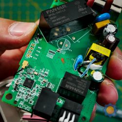
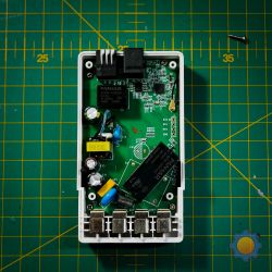
The SONOFF TH Elite 16A in which there are two conventional relays will be modified. Both are supplied with 5V and operate simultaneously. The larger 16A relay switches 220V from the device input to the output. In turn the other FANHAR FH38-1CSGH is a smaller relay also powered by 5V and operates the dry contacts output.
Both relays will be removed from the board. Then I will use the 5V supply which originally supplied the smaller relay to control the SSR module.
For this I will use a cable about 6 metres long which will be connected to the 5V supply after the small relay and on the other side to the SSR input.
Theoretically everything looks simple and makes sense ...
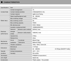
The FANHAR FH38-1CSGH is powered by 5V but due to the fact that it is a traditional relay I assume that there can be more than 100mA current.
This I guess from the specifications of this relay, whose photo I pasted.
On the other hand, most of the available SSRs in their documentation states that the control current should be in the range of 3-30V and not exceed 10mA.
Please help now ... if I connect the SSR using 5V which previously supplied a standard relay, will this work correctly and the SSR will only draw as much current as it needs? Do I have to measure the current from that source and use a resistor which will reduce the current of this 5V to the specification of the SSR, i.e. 10mA?
Please also give me suggestions on the choice of the SSR itself. While What I know is that it will be an SSR controlled by DC 5V and will output 220V and the load at 2000W is probably about 9-10A so I will choose something with a reserve of say 20-25A. I have also read about cheap counterfeits so I am determined to buy a more expensive SSR module.
If my SSR control voltage is 5V, is it safer for me to buy an SSR with a range of 3V? Is an SSR with a control range starting at 4V also OK? I have seen a few Panasonic models that have a control range starting at 4V and I am not sure if this will work correctly.
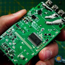
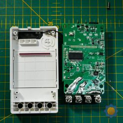
I will also upload some "borrowed" pictures of the Sonoff device itself.
Generally the whole idea is that the temperature sensor and the smart part including the display is located in a different place than the heater. In addition, I want to get rid of the traditional transmitters because of the sound they generate. The smart device will be powered from a different socket and will only be connected to the heater by a 5V feeder cable which will activate the SSR.
 .
.
Till now, my knowledge was sufficient to successfully complete several projects.
This time I will have to ask more experienced colleagues for help, because I'm getting into topics related to electronics and I don't feel very confident here.
The current project is a modification of an Adax Neo 2000W electric heater so that it becomes smart and works in my Sonoff system.
It is an additional heater that works when the central heating is not working.
The whole system associated with this heater will consist of the following components:
1. electric heater Adax Neo 2000W with the original control removed (only the heating element and thermal protection remain)
2. The heart of the system will be the SONOFF TH Elite 16A. It is a smart temperature and humidity sensor/actuator.
3. Connected to the SONOFF TH Elite 16A temperature and humidity sensor SONOFF THS01
4. Solid State Relay (SSR)
The heater is mounted on the wall near the power socket. The SSR will be mounted in the radiator itself on the right hand side where the power/control circuit is currently located. This is the coolest place on the radiator as the heater is on the left and a little higher than the circuit. One option is to mount the SSR on the outside of the radiator. However, it seems more sensible to use the place where the control is currently located. To make it even funnier, the heater is switched on using the SSR only it is part of the whole power circuit board from which runs a ribbon to the control circuit.
On the other hand, the smart part and the temperature sensor will be located approx. 3 metres away from the heater in a straight line and approx. 6 metres by the length of the walls.
The SONOFF TH Elite 16A in which there are two conventional relays will be modified. Both are supplied with 5V and operate simultaneously. The larger 16A relay switches 220V from the device input to the output. In turn the other FANHAR FH38-1CSGH is a smaller relay also powered by 5V and operates the dry contacts output.
Both relays will be removed from the board. Then I will use the 5V supply which originally supplied the smaller relay to control the SSR module.
For this I will use a cable about 6 metres long which will be connected to the 5V supply after the small relay and on the other side to the SSR input.
Theoretically everything looks simple and makes sense ...
The FANHAR FH38-1CSGH is powered by 5V but due to the fact that it is a traditional relay I assume that there can be more than 100mA current.
This I guess from the specifications of this relay, whose photo I pasted.
On the other hand, most of the available SSRs in their documentation states that the control current should be in the range of 3-30V and not exceed 10mA.
Please help now ... if I connect the SSR using 5V which previously supplied a standard relay, will this work correctly and the SSR will only draw as much current as it needs? Do I have to measure the current from that source and use a resistor which will reduce the current of this 5V to the specification of the SSR, i.e. 10mA?
Please also give me suggestions on the choice of the SSR itself. While What I know is that it will be an SSR controlled by DC 5V and will output 220V and the load at 2000W is probably about 9-10A so I will choose something with a reserve of say 20-25A. I have also read about cheap counterfeits so I am determined to buy a more expensive SSR module.
If my SSR control voltage is 5V, is it safer for me to buy an SSR with a range of 3V? Is an SSR with a control range starting at 4V also OK? I have seen a few Panasonic models that have a control range starting at 4V and I am not sure if this will work correctly.
I will also upload some "borrowed" pictures of the Sonoff device itself.
Generally the whole idea is that the temperature sensor and the smart part including the display is located in a different place than the heater. In addition, I want to get rid of the traditional transmitters because of the sound they generate. The smart device will be powered from a different socket and will only be connected to the heater by a 5V feeder cable which will activate the SSR.


 .
.


