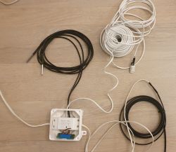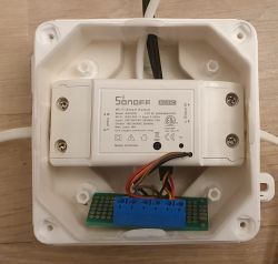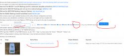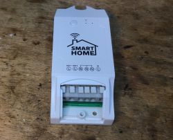
Today we are uploading Tasmota to a device that is essentially a repainted Sonoff Dual R2, a relay module commercially available under the name WS-05H1. The equipment was given to me by a reader so that I could change the firmware and take a few photos. As usual, first a presentation of the interior, then programming and finally a template. Here we go!
Purchase of WS-05H1
The equipment was purchased in our country for PLN 60:
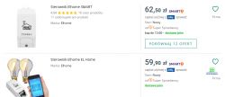
Here are screenshots from the seller's description:
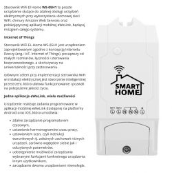
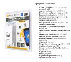
I won't even test the eWeLink application, it has already been done, we will change the firmware immediately.
Let's see what we get in practice:
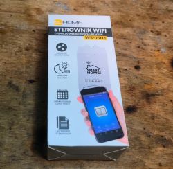
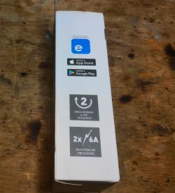
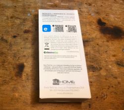
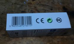
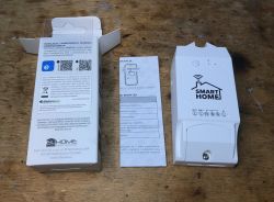
Instruction:
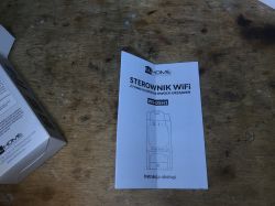
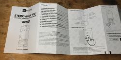
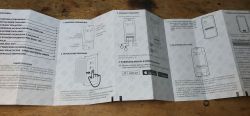
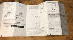
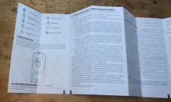
And the driver itself:
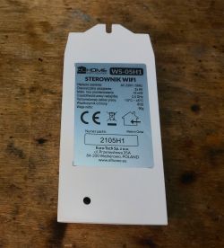

Interior of WS-05H1
It is customary to pry the lid off. This time, however, it is a bit different. This device is distinguished by the presence of an isolated flyback power supply. Smaller modules contain non-isolated step down converters.
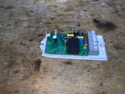
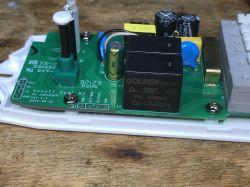
The PCB has a programming connector (without IO0) and additional signals from the buttons - it's worth doing DIY.
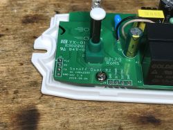
The interior is not that bad, I see a filter, a varistor, a fuse, the CY capacitor from the power supply (connects the secondary and primary sides) is also present:
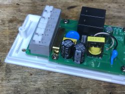
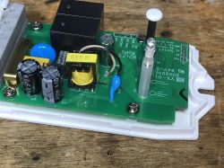
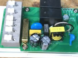
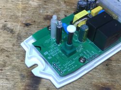
The bottom of the PCB - high current paths are tinned:
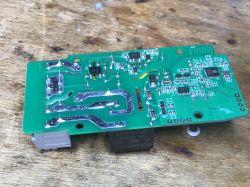
On the bottom there is a rectifier bridge and a flyback controller:
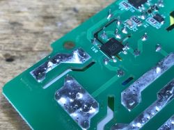
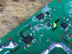
The power supply is based on CSC7102C, which I have already seen in another Sonoff product:
Sonoff Basic ZBR3, the famous Zigbee version of the relay. Interior, diagram
Second photo:
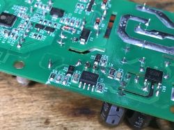
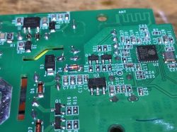
Still standard, J3Y transistors controlling the relays with protection diodes:
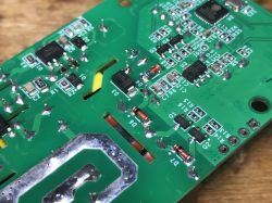
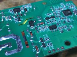
A little further you can see LDO 3.3V and ESP, this time on the PCB:
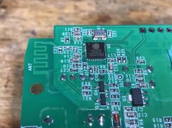
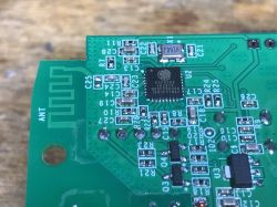
There is no external Flash chip here because it is ESP8285, i.e. with built-in memory.
Firmware change
As in the topic about the light switch:
SmartLife switch - test, interior and programming of a WiFi light switch
We solder the cables:
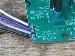
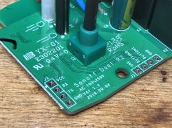
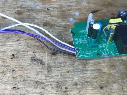
And now note - we need GPIO0 to enter the bootloader mode, but it is output to Button0:
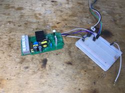
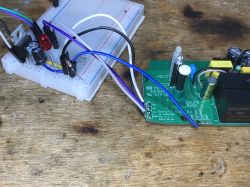
And that's it - here's the list of GPIO roles:
Pin	Function
GPIO10	Push Button
GPIO00	Pin "button 0" on expansion header
GPIO09	Pin "button 1" on expansion header
GPIO12	Relay #1 and red color on LED
GPIO05	Relay #2 and green color on LED
GPIO13	Blue Status LED
Summary
I've seen modules twice as small, also with two relays, but fitting into a standard box... but it's probably not bad anyway. There is ESP on board, you can upload the proven Tasmota and the product will work without the cloud and fully locally on our network, it will also pair easily with Home Assistant.
In addition, we have two GPIOs available on the connector, you could even connect a DHT11 or another sensor, Tasmota has supported this for a long time. There is no fear of shock, the power supply is isolated and there is a flyback, similar to another Sonoff product previously discussed.
Do I recommend it? It depends on how much space we have. Or maybe you will tell me? Do you prefer smaller modules, or do you also use this type of relays in "large" housings?
Cool? Ranking DIY Helpful post? Buy me a coffee.


