logo elektroda
logo elektroda
X
logo elektroda

Integrating Taipow 30W Plafon Ceiling Lamp RGBCW with Home Assistant: BL-M5 V1.2/BL602 SoC Issues

piebru 2709 16
ADVERTISEMENT
  • Helpful post
    #1 20519775
    piebru
    Level 3  
    Hi wonderful people,

    I use Home Assistant and just bought a RGB-CW ceiling light, hoping to integrate it via Tuya or by a custom firmware upgrade.
    https://www.amazon.it/gp/product/B0B689DJVZ/ (I'm not affiliated in any way).

    However, to me it seems the beginning of a rabbit hole, as:
    1. It isn't supported by the Tuya app, but by an app called "Surplife".
    2. I was not able to add this lamp in the Tuya app.
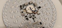
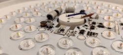
    3. The SoC board is marked BL-M5 v1.2
    4. The SoC is a BL602C20, for which Bouffalo says: “BL602 supports the use of ECC-256 signed images to provide secure boot protection”.
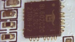
    Integrating Taipow 30W Plafon Ceiling Lamp RGBCW with Home Assistant: BL-M5 V1.2/BL602 SoC Issues

    5. Tuya CloudCutter did not exploit this device.
    6. TinyTuya didn't find this device after adding it to my LAN.
    7. I would like to use hid_download_py, but I wasn't able to find TX, RX and RST. The only pins I found marked on the LED board and on the SoC board are: 3.3v, GND, DAT, CLK. I feel dumb, but I wasn't able to find the pinout of the SoC board (BL-M5 v1.2).

    The lamp performs very good with its RF remote, and it isn't easy to find such products, thus before returning it to the seller I would make other tests, here are my questions:
    A. How can I try to attach a FTDI adapter and flash the BL602 firmware (.bin)?
    B. Do you think the "ECC-256 signed image" could prevent booting a custom firmware?
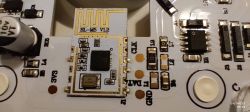

    Integrating Taipow 30W Plafon Ceiling Lamp RGBCW with Home Assistant: BL-M5 V1.2/BL602 SoC Issues Integrating Taipow 30W Plafon Ceiling Lamp RGBCW with Home Assistant: BL-M5 V1.2/BL602 SoC Issues Integrating Taipow 30W Plafon Ceiling Lamp RGBCW with Home Assistant: BL-M5 V1.2/BL602 SoC Issues
  • ADVERTISEMENT
  • #2 20519784
    p.kaczmarek2
    Moderator Smart Home
    Hello,
    you need to know where RX/TX pads are.
    Cloudcutter doesn't support BL602.

    We need to either find documentation of BL-M5 V1.2 or desolder that one module with hot air (or with a tricky method with cheap soldering iron) and read the markings on the other side of module PCB.

    Have you seen our WiFi module desoldering tutorials?

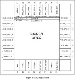
    You could also try probing if you have tiny probes, because we know the pinout of BL602 in QFN, and see where programming pads are going...

    Added after 1 [minutes]:

    Here is pinout of BL602C/E QFN32:
    Integrating Taipow 30W Plafon Ceiling Lamp RGBCW with Home Assistant: BL-M5 V1.2/BL602 SoC Issues
    do you have probes and the precision to do checking where each GPIO connects?

    Added after 49 [seconds]:

    Wait, here is pinout:
    https://www.elektroda.com/rtvforum/topic3949764.html#gallery-6

    Added after 1 [minutes]:

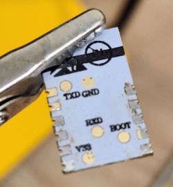
    Oh no, it looks like programming pads are under the board:
    Integrating Taipow 30W Plafon Ceiling Lamp RGBCW with Home Assistant: BL-M5 V1.2/BL602 SoC Issues
    You can flash it with OpenBL602 but that would require desoldering the module.
    Helpful post? Buy me a coffee.
  • ADVERTISEMENT
  • #4 20519793
    p.kaczmarek2
    Moderator Smart Home
    piebru wrote:

    7. I would like to use hid_download_py, but I wasn't able to find TX, RX and RST. The only pins I found marked on the LED board and on the SoC board are: +3.3v, GND, DAT, CLK. I feel dumb, but I wasn't able to find the pinout of the SoC board (BL-M5 v1.2).


    No, you can do it that way:


    Helpful post? Buy me a coffee.
  • #5 20521426
    piebru
    Level 3  
    >>20519784
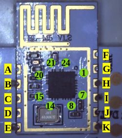
    I managed to map the board pinout with 13 out of 24 pins of the BL602 SoC:

    Board - SoC
    A - 10
    B - 3
    C - 4
    D - 11
    E - 8,21,22 - 3.3v
    F - 5
    G - 15
    H - 24 - CLK
    I - 23 - DAT
    J - 2
    K - 20 - GND

    Integrating Taipow 30W Plafon Ceiling Lamp RGBCW with Home Assistant: BL-M5 V1.2/BL602 SoC Issues

    The FCC docs aren't of much help, as it shows an "old" prototype: https://fccid.io/2A9HW-BL602

    On the board, only B, E, H, I, K seem soldered. TX, RX and RST (GPIO8?) may be accessible by some unsoldered board pins, but we will know only after desoldering.
    I don't have an air desolder and will try the poor man post-apocalyptic way :-)

    Meanwhile, is there other info I can contribute before the surgery?
    Piero
  • ADVERTISEMENT
  • #6 20521451
    p.kaczmarek2
    Moderator Smart Home
    What kind of "I2C" LED driver is used for this lamp? SM2135?

    piebru wrote:

    I don't have an air desolder and will try the poor man post-apocalyptic way :-)

    This is the way:


    Helpful post? Buy me a coffee.
  • #7 20521482
    piebru
    Level 3  
    Thank you for the video link, my 70yo eyes and hands will try to get lucky :-)
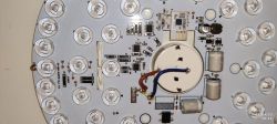
    There are 3 LED driver chips, all 3 are BP5758 https://github.com/dbuezas/esphome-bp5758
    CLK and DAT are connected with two pins of the first (labelled Q1) LED driver.
  • ADVERTISEMENT
  • #8 20521483
    p.kaczmarek2
    Moderator Smart Home
    How are they connected?

    Where are connected CLK and DAT pins of remaining BP5758?
    Helpful post? Buy me a coffee.
  • #9 20521528
    piebru
    Level 3  
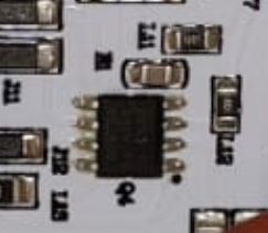
    I assumed pin 1 on the LED drivers is the one marked with a black dot on the PCB.

    Integrating Taipow 30W Plafon Ceiling Lamp RGBCW with Home Assistant: BL-M5 V1.2/BL602 SoC Issues

    Added after 4 [minutes]:

    >>20521483
    While Q1 (the topmost) pins 3 and 4 are connected directly to the corresponding SoC pins, Q3 and Q4 pins are connected through resistors to the same SoC pins.

    Added after 5 [minutes]:

    Forgot the picture, sorry :-(

    Integrating Taipow 30W Plafon Ceiling Lamp RGBCW with Home Assistant: BL-M5 V1.2/BL602 SoC Issues
  • #10 20522520
    piebru
    Level 3  
    Desoldered the board with as little damage as possible, I hope it will work once soldered again on the PCB.

    All pins letters and numbers are referred to my mapping above: TX is "F" and RX is "G". BOOT seems not connected to a board pin, but it's on the SoC pin "15" that is connected with the nearest pull resistor (near the xtal). A temporary reset should be possible using a thin probe.

    I would like to install Tasmota, but I fear the unusual LED drivers.
    Can you confirm what .bin I can try first?
  • #11 20522545
    p.kaczmarek2
    Moderator Smart Home
    BP5758 is supported, you just need to know which GPIO for BL602 are used for SDA and SCL and then maybe remap colours.
    You have the flashing procedure shown here:
    https://www.youtube.com/watch?v=L6d42IMGhHw
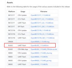
    Binaries are here:
    https://github.com/openshwprojects/OpenBK7231T_App/releases/
    Integrating Taipow 30W Plafon Ceiling Lamp RGBCW with Home Assistant: BL-M5 V1.2/BL602 SoC Issues
    Helpful post? Buy me a coffee.
  • #12 20522580
    piebru
    Level 3  
    Thanks, it seems one can flash it even without desoldering.

    So these are the most interesting pins in this Taipow lamp:

    FTDI --> BL602 board --> BP5758
    -----------------------------------
    3.3V "E" -
    GND "K" -
    TX "F" -
    RX "G" -
    BOOT resistor lead near the xtal
    - DAT SDA (pin 3)
    - CLK SCL (pin 4)

    In a few days I will try to flash the SoC board after re-soldering it on the PCB, just to see if it can be flashed to Tasmota without de-soldering.
  • #13 20522657
    p.kaczmarek2
    Moderator Smart Home
    This is a very good news. If RX/TX is indeed connected to F and G, and BOOT signal is available on the resistor, then it should be possible to flash this device without desoldering the WiFI module.
    Helpful post? Buy me a coffee.
  • #14 20542665
    piebru
    Level 3  
    Some not-so-good news, compensated by good news, so I'm happy. Here's why.

    Not-so-good news: I damaged the SoC board PCB tracks while de-soldering. I will try to recover it, but it's not easy for me. I don't plan to buy more of these ceiling lamps, because these are too small for my usage.

    Good news: to be able to use this lamp, I did a brain transplant in favor of an old ESP32 board (Wemos Mini). I then managed to get the RGB-CW-WW show running with ESPhome, despite the odd three chips 5-channels drivers design, when in theory one driver should be enough. Maybe it has been designed this way to overcome heating or power issues.

    Once I installed ESPhome on the ESP32, I easily disguised other features into this sconce, such as mmWave radar human presence sensor, light sensor and maybe more to come.

    Here is the "light" relevant part of my ESPhome yaml configuration, so it can be ported to other platforms:

    substitutions:
    bp5758_data_pin: "GPIO21" # SDA. If you want to use I2C for other sensors, GPIO32 has been tested here.
    bp5758_clock_pin: "GPIO22" # SCL. If you want to use I2C for other sensors, GPIO33 has been tested here.
    rgbww_default_transition_length: "0.5s" # ESPhome default = 1s
    rgbww_cold_white_color_temperature: "6500 K" # Depending on the LED specs
    rgbww_warm_white_color_temperature: "2700 K" # Depending on the LED specs
    rgbww_boot_color_temperature: "4000 K" # Set your preference for this light
    rgbww_boot_brightness: "75%" # Set your preference for this light
    rgbww_restore_mode: ALWAYS_OFF

    bp5758d: # https://esphome.io/components/output/bp5758d.html
    # See BP5758D_EN_DS_Rev.1.1.pdf
    data_pin: ${bp5758_data_pin}
    clock_pin: ${bp5758_clock_pin}

    output:
    - platform: bp5758d # https://esphome.io/components/output/bp5758d.html
    id: output_red
    channel: 1
    current: 10
    - platform: bp5758d
    id: output_green
    channel: 2
    current: 10
    - platform: bp5758d
    id: output_blue
    channel: 3
    current: 10
    - platform: bp5758d
    id: output_warm_white
    channel: 4
    current: 10
    - platform: bp5758d
    id: output_cold_white
    channel: 5
    current: 10

    light:
    - platform: rgbww # https://esphome.io/components/light/rgbww.html
    name: "Light"
    id: light1
    default_transition_length: ${rgbww_default_transition_length}
    restore_mode: ${rgbww_restore_mode}
    color_interlock: True
    cold_white_color_temperature: ${rgbww_cold_white_color_temperature}
    warm_white_color_temperature: ${rgbww_warm_white_color_temperature}
    red: output_red
    green: output_green
    blue: output_blue
    warm_white: output_warm_white
    cold_white: output_cold_white

    ...


    This is a good foundation for custom automations placed on the edge, working even off-line from the Wifi or the server.
    I had a lot of fun in doing this. Also, I'm happy that in this way the community can free more devices from the cloud slavery and its privacy concerns :-)
  • #15 20542673
    p.kaczmarek2
    Moderator Smart Home
    Hello, what kind of the damage the module tracks has?
    Helpful post? Buy me a coffee.
  • #16 21328582
    yonubear
    Level 3  
    I know this is an old post but have you got this working? I have several of these lights and want to reflash and get them working with openbekten or esphome
  • #17 21328650
    p.kaczmarek2
    Moderator Smart Home
    I'd say just give it a go, we'll help you if there is an issue.

    BL602 tutorial:


    Helpful post? Buy me a coffee.

Topic summary

The discussion focuses on integrating the Taipow 30W Plafon RGB-CW ceiling lamp, which uses a BL-M5 V1.2 board with a BL602C20 SoC, into Home Assistant. The lamp is unsupported by the Tuya app and instead uses the Surplife app, complicating direct integration. Attempts to detect or control the device via Tuya CloudCutter and TinyTuya failed. The BL602 SoC supports secure boot with ECC-256 signed images, adding complexity to firmware flashing. The main challenge is locating the RX, TX, and BOOT pads for flashing, as only 3.3V, GND, DAT, and CLK pins are visibly marked. Community members provided BL602 QFN32 pinouts and suggested probing or desoldering the WiFi module to access hidden programming pads. The lamp uses three BP5758 LED driver chips connected via I2C (CLK and DAT lines), complicating firmware compatibility. After mapping 13 of 24 SoC pins and identifying TX and RX pins, flashing with Tasmota or ESPhome was considered feasible without desoldering. However, desoldering attempts caused PCB track damage. As a workaround, the lamp’s control was transplanted to an ESP32 (Wemos Mini) running ESPhome, successfully managing the RGB-CW-WW channels and integrating additional sensors like mmWave radar and light sensors. The discussion includes references to flashing procedures, firmware binaries, and pin mappings to aid others attempting similar integrations.
Summary generated by the language model.
ADVERTISEMENT