logo elektroda
logo elektroda
X
logo elektroda

[LF686C20] [BL602] Magic Home RGBW 12-24v 5-pin LED Strip Controller

divadiow 9450 84
ADVERTISEMENT
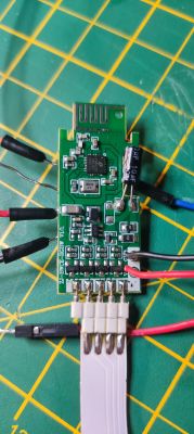
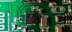
  • Presenting a familiar device, one I've seen around the forum, but this one is without an Ir receiver and comes with an LF686 chip, which is to be flashed as a BL602.

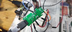
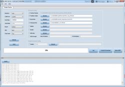
    I spent HOURS trying to get this to flash with my pogo pins and several different USB-TTL adaptors but I only got success after soldering all pads AND pulling BOOT from 3.3v rail on external PSU directly, not via V33 pad and 10k resistor. I also tried v 1.8.8 of the BLDevcube. Success was using 1.4.8.

    Ext 3.3v -> V33 pad
    Ext 3.3v -> 10k R -> BOOT pad
    Ext GND -> GND pad
    TTL RX -> TX pad
    TTL TX -> RX pad
    TTL GND -> Ext GND

    Post-flash there was no wifi, even using external 3.3v (and with BOOT unsoldered), but with the external DC jack connected, it all came up. I did not use V+ and GND pads on this board. I have read in another thread that someone had success flashing with 5V on V+.
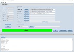
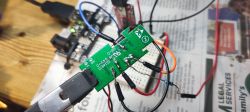
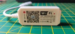
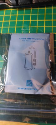
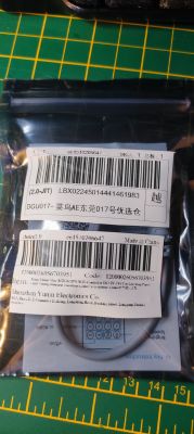
    BLDevCube software interface with selected options and a success message. Electronic board with soldered wires connected to a USB-TTL adapter. Magic Home RGBW controller board with soldered wires. Close-up of a circuit board with wires connected to various pads. Close-up of a circuit board with an LF686C20 chip. WiFi LED controller Magic Home with a label and QR code. White cable with DC connector on a green cutting mat with a centimeter scale. User instruction manual for Magic Home RGBW LED Controller in plastic packaging. Close-up of two packaging bags with product labels for electronic items.
    Product page for Magic Home Mini RGB RGBW WiFi Controller on AliExpress.

    I tried the device profile of this device but cleared the ir GPIO and used the GPIO Finder to see that pin 20 toggled something on/off
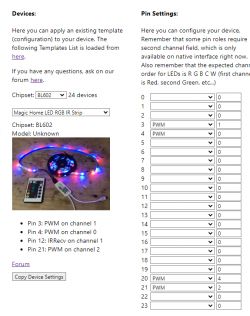
    Screenshot of the Magic Home LED controller configuration with BL602 chipset.

    Unfortunately the 4 pin RGB strip I used in testing did not have a W pin and the energizer 5-pin RGBW strip I also have didn't seem to match the RGB pinout, so I'm only reasonably confident this is the correct OBK template (should RGB be 0,1,2 and the W 3 or 4 (there's no C)?):

    Code: JSON
    Log in, to see the code

    Cool? Ranking DIY
    About Author
    divadiow
    Level 34  
    Offline 
    divadiow wrote 2749 posts with rating 472, helped 246 times. Live in city Bristol. Been with us since 2023 year.
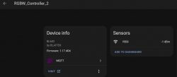
  • ADVERTISEMENT
  • #2 20886585
    p.kaczmarek2
    Moderator Smart Home
    So it's basically the strip controller from out video but with a different marking on the chip?


    I'm really curious what is the backstory behind LF686C20, is it made by the same company as BL602?
    Helpful post? Buy me a coffee.
  • #3 20887595
    divadiow
    Level 34  

    p.kaczmarek2 wrote:
    So it's basically the strip controller from our video but with a different marking on the chip?


    Indeed, but without the infrared option on the PCB and 5 pins.

    Added after 6 [minutes]:

    p.kaczmarek2 wrote:
    I'm really curious what is the backstory behind LF686C20, is it made by the same company as BL602?


    Me too. Maybe I'll email Leapfive and ask.
  • #4 20904742
    mavrov
    Level 4  
    Hi there. First of all thank you for all the amazing work already done! I have a dumb question, but i have to ask it. It's about the external power supply. Can I use the USB TTL as said extenral power supply ? Or i need an actual external power supply? I am fairly new to the board reflashing. I have done it couple of times with CB3S boards, but i am wondering if this thing is actually different or i am just not used to the terminology?

    Random thought after posting this...
    Can i use Arduino / ESP board as 3.3V power supply ? That would make my life so much easier if it's okay :)
  • #5 20904764
    divadiow
    Level 34  
    mavrov wrote:
    I have a dumb question, but i have to ask it. It's about the external power supply. Can I use the USB TTL as said extenral power supply ? Or i need an actual external power supply?


    a good question. I have had success flashing a couple of smaller devices when I first started, but now I just use an external (NOT the 3.3v from the USB-TTL) wherever I can to save wondering if my fails are related to power. For a couple of £ you can the equivalent of this kit I mention in my post here https://www.elektroda.com/rtvforum/topic4027954.html from Ali Express or many outlets.

    ELEGOO electronic kit with wires, resistors, capacitors, LEDs, and other components on a white background.

    Added after 3 [minutes]:

    in fact in the pic above you can see my red power jumper is coming off the power rail of the breadboard, where the MB102 is attached, and not one of the ttl pins

    Close-up of a circuit board with various connected wires, placed on a workbench.
  • #6 20904801
    mavrov
    Level 4  
    I think i get the idea. I was also looking at a board like that for the power supply, but now i am conviced i will get one to mitigate power issues as you mentioned. In the meantime i will try with an Arduino board 3.3V pin just for the sake of trying.

    Another thing i saw in the video above for the LED strip - i saw there the board was powered directly from the 12V power supply and only RX, TX, GND connected to the USB.

    This is also an idea, but kind of afraid to try it. Don't want to mess up something and fry a port on my laptop.

    Anyway... Thanks for the advice again. I will try it later when i finish work (and post the results), because i feel the itch :D I bought 4 RGBW drivers and they are waiting for me to figure how reflash with something civilized and put them to use.
  • #7 20904831
    divadiow
    Level 34  
    sure.

    I have used the 12v DC jack from a standard mains PSU with barrel connector (one I found in a drawer with a connector that fits) for flashing some LED strip controllers. I've yet to blow anything. I always make sure my TTL adaptor is grounded to the breadboard PSU GND as well as the GND pad on the PCB, so there's a common ground. I think this is correct, I'm no expert.
  • ADVERTISEMENT
  • #8 20904835
    p.kaczmarek2
    Moderator Smart Home
    It is possible to use Arduino or NodeMCU as both USB to UART converter and a power supply, but in order to do that, you need to put ESP (or Atmega) in the RESET state, by shorting RESET to ground.
    Helpful post? Buy me a coffee.
  • ADVERTISEMENT
  • #9 20904854
    mavrov
    Level 4  
    divadiow wrote:
    I always make sure my TTL adaptor is grounded to the breadboard PSU GND as well as the GND pad on the PCB, so there's a common ground


    Never liked electricity so i will skip this scenario altogether :D

    p.kaczmarek2 wrote:
    It is possible to use Arduino or NodeMCU as both USB to UART converter and a power supply, but in order to do that, you need to put ESP (or Atmega) in the RESET state, by shorting RESET to ground.


    This I like. This is doable. I will try it. Thank you for the input.

    Edit: It worked like charm. Arduino mega as ext. Psu put in reset mode. No issues whatsoever.
    Thank you again.
    Now... Let's concert the other 3 and start the hard part... Convincing the wife that she'll like what I have in mind
  • ADVERTISEMENT
  • #10 20906564
    p.kaczmarek2
    Moderator Smart Home
    I may forgot to say that earlier, but if you have LF686/BL602 device and consider flashing it, please take a firmware backup first. I am actively looking for BL602 firmware dumps. Just keep it in mind.
    Helpful post? Buy me a coffee.
  • #11 20906586
    divadiow
    Level 34  

    Did you manage to backup the firmware for the device in this thread?

    What is the procedure for backing up a BL602? Can we only flash with bldevcube?
  • #12 20906612
    p.kaczmarek2
    Moderator Smart Home
    I don't know much about it, I haven't tried it yet. There is a similiar thread where user used other tool:
    https://www.elektroda.com/rtvforum/topic4027953.html

    As far as I know there is also some kind of advanced option that allows read in BLDevCube, but I am not sure about it
    Helpful post? Buy me a coffee.
  • #13 20906673
    divadiow
    Level 34  
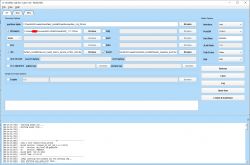
    ah yes. looks like I downloaded that on the 29th December but immediately forgot, then proceeded to flash the device with OpenBL602. I've another Magic Home BL602 untouched. Here is the boot log attached using BLDevCube 1.8.8 and UART rate 2000000

    Screenshot of Bouffalo Lab Dev Cube 1.8.8, displaying settings for flashing the BL602 device and a boot log.

    I'll try factory dump now using https://github.com/spacemeowx2/blflash/releases/download/v0.3.5/blflash-windows-amd64.exe
  • #15 20906766
    p.kaczmarek2
    Moderator Smart Home
    Is it full dump? This device has 2MB flash, right? Hmm. Maybe you need to specify the size.
    Helpful post? Buy me a coffee.
  • #16 20906779
    divadiow
    Level 34  
    hmm, unsure. during the dump it does give a progress/total bar. 911.50kib is total.

    I don't see any size option switches for the exe. I'll play more later

    Screenshot of a terminal showing a flashing procedure with a progress bar and data transfer details.

    Added after 3 [minutes]:

    I'm trying different speeds and the total is the same for all so far apart from 9600 baud

    Windows console showing the result of a blflash command with data dump progress.

    Added after 8 [minutes]:

    getting closer

    File name and properties of a binary file on a Windows file list.

    Added after 6 [minutes]:

    oh i see, the numbers im specifying are the size of flash to dump (maybe?), not the speed, if setting one set of numbers. Screenshot of a terminal showing the process of dumping data from a device to a binary file.

    Added after 53 [minutes]:

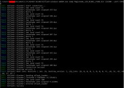
    I see from the datasheet that onboard flash is optional. With this command, which includes the --<parameters>, I get a 1mb dump

    blflash-windows-amd64.exe dump MagicHome_LED_BL602_LF686_2.bin --initial-baud-rate 115200 --baud-rate 115200 --port COM10


    https://www.leapfive.com/wp-content/uploads/2020/09/LF686-Datasheet.pdf
  • #17 20907219
    p.kaczmarek2
    Moderator Smart Home
    So can you try to use this command to dump 2MB?
    Screenshot of a terminal with data transmission information to a device via COM10 port.
    Helpful post? Buy me a coffee.
  • #18 20907230
    divadiow
    Level 34  
    Here's the 2MB using deleted. was junk
    blflash-windows-amd64.exe dump 2MB_MagicHome_LED_BL602_LF686.bin 115200 2097152 --port COM10
    .

    No idea if it's complete.
  • #19 20907736
    divadiow
    Level 34  

    >>20904854
    Glad you had success @mavrov.

    What device did you flash, and are the ones you have all the same?
  • #20 20909944
    mavrov
    Level 4  

    I still haven't gotten around to flashing the rest, so I can make a dump of one of those if you still need it. I just need some docs/links on how to do it, but I can make one before flashing.

    Added after 1 [minutes]:

    >>20907736

    Magic Home RGBW LED controller, same as in the videos above.
  • #21 20915017
    tech_fr3ak
    Level 2  
    I have two modules with me, the same version as the OP. I am not able to make it work.

    Connections:
    - RX to TX
    - TX to RX
    - VCC to 3V3
    - GND to GND
    - Boot to 10k resistor to 3V3

    Screenshot of Bouffalo Lab Dev Cube software showing configuration for flashing an IoT module.
    Flashing part seems successful, but then, as per the log, it seems stuck in a boot loop and keeps crashing all the time.
    No AP

    What am I missing here? Attaching logs, please check.
    Versions tried: 1.17.376, 1.17.398, 1.17.413.

    Earlier, I was getting AP as LEDXXX, which I don't see now, so for sure flashing is done.
  • #22 20915025
    divadiow
    Level 34  

    I *think* I had a boot loop until I powered it off the 12V DC adapter through the barrel connector. I have had issues with some devices anyway.
  • #23 20915028
    p.kaczmarek2
    Moderator Smart Home
    That's as @divadiow say. It has been discussed several times on our forum already, but you need to power your BL602 with a good power supply to get stable WiFi, especially STA mode.
    Helpful post? Buy me a coffee.
  • #24 20915029
    divadiow
    Level 34  

    divadiow wrote:
    Post-flash there was no Wi-Fi, even using external 3.3V (and with BOOT unsoldered), but with the external DC jack connected,


    Oh yeah. This was the device
  • #25 20915036
    p.kaczmarek2
    Moderator Smart Home
    You can look at my topic about BL602 modules, here:
    https://www.elektroda.com/rtvforum/topic3945435.html#20905200
    Posts 13, 14, 15 - that user also had a very similiar issue and powering with a good power supply helped.

    It's just that WiFi operation requires more current than just flashing device, so you may have flashed your BL602 successfully, but you still not able to run it.
    Helpful post? Buy me a coffee.
  • #26 20915156
    tech_fr3ak
    Level 2  
    Thanks for the input. Yes, I am using a 12V 5A PSU, powering via the barrel only, not from the USB flasher/PC.

    It's just that I was not seeing the AP, so I connected to the PC for debug.

    Also, for me, the boot reason is watchdog, as per the log.

    Boot Reason:        BL_RST_SOFTWARE_WATCHDOG


    I had ticked the Factory Params box. Can that be the issue? I flashed again without checking that, but it's still the same.
  • #27 20918503
    mavrov
    Level 4  
    I have another problem with my second device. Flashed okay, copied the config from the first one and from the Web interface works like a charm. Connecting it with HA on the other hand gives me only RSSI sensor, but no light controls. What am I missing?
  • #28 20918515
    p.kaczmarek2
    Moderator Smart Home
    @mavrov what is the config? Remember that you need to redo HASS discovery after every config change.
    Helpful post? Buy me a coffee.
  • #29 20918534
    mavrov
    Level 4  
    Display of WiFi and MQTT connection status. User interface for RGBW controller showing device info and sensors.
    This is the device in question. What part of the config you would like me to show you?

    Going back and forth between devices i lost control of my other device, so both now are showing just RSSI.

    Edit: Figured out what the issue was. And how to fix it. In order to make HA detect light control I had to enable flag 24( for simulating white with RGB only). Then again ran HA discovery and the light was there. This in turn made my led strip not use the white channel (which is expected behaviour of the flag). Then after having the light control already in HA I disabled the flag again and ran discovery again. This didn't remove the control this time and made the strip use the white Channel also.
    So in summary for everyone struggling with the light control not appearing in HA for RGBW lights:
    1. Enable flag 24 for forcing white with only RGB.
    2. Do a HA discovery
    3. Disable the flag
    4. Do HA discovery again
    5. Verify each channel is working properly

    Thanks again for the wonderful work on the firmware!
    1)
  • #30 20918602
    hubiverse
    Level 3  
    Anyone having issue getting BL602 to update via OTA? I get stuck after hitting start OTA. Prompts “starting OTA” and just sits there.

Topic summary

The discussion revolves around the LF686C20 LED strip controller, which utilizes the BL602 chip. Users share their experiences flashing the device, noting challenges with power supply and connectivity. Successful flashing often required external power sources, with some users achieving results by using Arduino boards or dedicated power supplies. Issues with WiFi connectivity were common, particularly when using mixed WPA2/WPA3 security settings. Users also discussed the importance of backing up firmware before flashing and shared methods for configuring pin assignments for RGBW control. The conversation highlights the need for stable power during operation and the potential for IR control, although some users reported difficulties in getting it to work. Additionally, there were inquiries about the missing components on the PCB and their implications for functionality.
Summary generated by the language model.
ADVERTISEMENT