Hello,
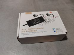
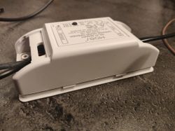
This is a teardown for a cheap garage door controller device bought on Aliexpress. It has a BK7231T / WB2S chip.
It requires soldering to flash OpenBK.
Info Summary:
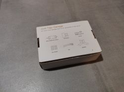
Model/SKU from Box: MS-102
Model/Revision from the Board: HG041-20211220
Chip: BK7231T / WB2S
Rated Voltage: 90V-250V
Relays Qty: 1
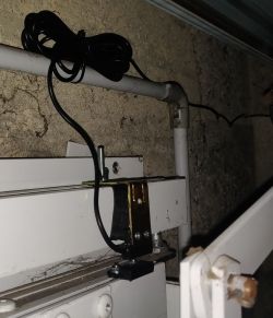
Binary sensor: 1
Buttons: 1
MCU/Firmware Version: unknown
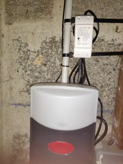
I use it for a Sommer Duo Vision 500 having a single open/stop/close button.
1. Open the case
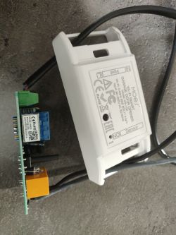
First open the plastic case. It has 4 clips, two on each side.
2. Solder wires
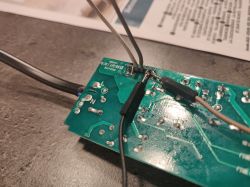
I'm not proud of my work, but it demonstrates it's doable by someone who only did soldering at highschool.
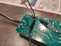
You need to solder rx, tx, +3.3 and gnd on the following pins. According to WB2S datasheet, the pin numbers we are looking for are :
3. Flash
Be sure to use a 3.3V alimentation and proceed to flashing. Follow up to date instructions from openshwprojects/OpenBK7231T_App Github page.
As of today, the recommended procedure is to use the GUI flash tool.
I had to use a computer running Windows because the Linux version failed to flash and I didn't found a workaround.
4. Configure
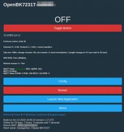
Connect to the "Open_BenkenXxxxx" SSID Network and open your browser to http://192.168.4.1.
In Config > Configure Module, set the following pinout:
In Config > Change Startup Command, set the following command:
Explanation:
backlog: let us write one line with a bunch of commands
setChannelType 1 OpenClosed_Inv
SetChannelLabel 0 Button
SetChannelLabel 1 Sensor
addChangeHandler ChannelButton != 0 addRepeatingEvent 0.5 1 setChannel 0 0 : simulate a stateless button, each time the button is activated, it is deactivated 0.5s later
Finally, restart the device.
Additional pictures


This is a teardown for a cheap garage door controller device bought on Aliexpress. It has a BK7231T / WB2S chip.
It requires soldering to flash OpenBK.


Info Summary:
Model/SKU from Box: MS-102
Model/Revision from the Board: HG041-20211220
Chip: BK7231T / WB2S
Rated Voltage: 90V-250V
Relays Qty: 1
Binary sensor: 1
Buttons: 1
MCU/Firmware Version: unknown
I use it for a Sommer Duo Vision 500 having a single open/stop/close button.


1. Open the case
First open the plastic case. It has 4 clips, two on each side.


2. Solder wires
I'm not proud of my work, but it demonstrates it's doable by someone who only did soldering at highschool.
You need to solder rx, tx, +3.3 and gnd on the following pins. According to WB2S datasheet, the pin numbers we are looking for are :
| 1 | VBAT | Power supply pin (3.3 V), which is connected to the VBAT pin on the internal IC | 3 | GND | Power supply reference ground pin | 5 | 1RX | UART1_RXD, which is used as a user-side serial interface pin and is connected to the P10 pin on the internal IC | 7 | 1TX | UART1_TXD, which is used as a user-side serial interface pin and is connected to the P11 pin on the internal IC |


3. Flash
Be sure to use a 3.3V alimentation and proceed to flashing. Follow up to date instructions from openshwprojects/OpenBK7231T_App Github page.
As of today, the recommended procedure is to use the GUI flash tool.
I had to use a computer running Windows because the Linux version failed to flash and I didn't found a workaround.
4. Configure
Connect to the "Open_BenkenXxxxx" SSID Network and open your browser to http://192.168.4.1.
In Config > Configure Module, set the following pinout:
| P6 (PWM0) | Btn | 1 | 0 | P7 (PWM1) | WifiLED | P24 (PWM4) | Rel | 0 | P26 (PWM5) | dInput_NoPullUp_n |
In Config > Change Startup Command, set the following command:
backlog setChannelType 1 OpenClosed_Inv; SetChannelLabel 0 Button; SetChannelLabel 1 Sensor; addChangeHandler ChannelButton != 0 addRepeatingEvent 0.5 1 setChannel 0 0Explanation:
backlog: let us write one line with a bunch of commands
setChannelType 1 OpenClosed_Inv
SetChannelLabel 0 Button
SetChannelLabel 1 Sensor
addChangeHandler ChannelButton != 0 addRepeatingEvent 0.5 1 setChannel 0 0 : simulate a stateless button, each time the button is activated, it is deactivated 0.5s later
Finally, restart the device.
Additional pictures


Cool? Ranking DIY


