logo elektroda
logo elektroda
X
logo elektroda

How to control F&F relays on DIN rail with ESP8266?

shady79 1290 22
ADVERTISEMENT
Treść została przetłumaczona polish » english Zobacz oryginalną wersję tematu
  • #1 18257677
    shady79
    Level 13  
    Welcome,

    I would like to do a lighting control in my house, and to make it look nice I would like to use DIN rail mounted F&F relays. The problem is that they have a 24VDC coil. Controlling from the ESP8266 is a bit of a problem in this case. Can anyone recommend anything on this subject? Some sort of logic level converter? The simplest thing would probably be to give a transistor and use it to drive a relay, but that's a bit of a pain - I'd like to make it as simple as possible. It would probably be best to use a PLC of some sort.
    A grenton system is nice but the price ranges are cosmic ;) .
  • ADVERTISEMENT
  • #2 18257695
    jakubek56
    Level 32  
    Even if the coils of this relay were at 3.3V they would still draw too much current from the ESP output.
    The only solution is a transistor.
    Using a PLC instead of an ESP AND a transistor is several tens of times more expensive.
  • #3 18257948
    shady79
    Level 13  
    does anyone know any ready-made modules with transistors that could be used? Making such a board isn't too much of a problem, but if there was something ready-made and with e.g. MCP23017 it would be a great thing:) .
  • #4 18260683
    khoam
    Level 42  
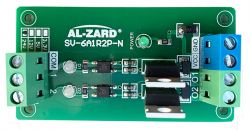
    On ali there are single and dual channel modules with optocouplers (necessary in this case) with 3V3 logic control. Images below - you need to search under "Optocoupler Isolation Module Driver" for the 3V3 version.

    How to control F&F relays on DIN rail with ESP8266?
    .
    How to control F&F relays on DIN rail with ESP8266?
    .

    Added after 38 [seconds]:

    shady79 wrote:
    e.g. still with MCP23017 would be great:)
    .
    I couldn't find any such.
  • ADVERTISEMENT
  • #6 18261126
    shady79
    Level 13  
    khoam wrote:
    On ali there are single and dual channel modules with optocouplers (necessary in this case) with 3V3 logic control. Images below - you need to search under "Optocoupler Isolation Module Driver" for the 3V3 version.

    How to control F&F relays on DIN rail with ESP8266?
    .
    How to control F&F relays on DIN rail with ESP8266?
    .

    Added after 38 [seconds]:

    shady79 wrote:
    e.g. still with MCP23017 would be great:)
    .
    I have not found any such.


    well this is an interesting option.;)
  • #7 18262217
    krzbor
    Level 27  
    To control a 24vDC relay all you need is one transistor, a 1k resistor and a diode for the surge on the relay. I don't know why separate modules are needed. Such a thing can easily be assembled on a universal board. I don't know how you want to build a circuit based on ESP and where to get power for the relay (24V) and ESP (3V). I personally switched to SONOFF modules, e.g. Sonoff Basic. They can be freely reprogrammed and have what you need: power supply, ESP and relay. There are even DIN rail mounts for Sonoff. I recently bought (but haven't installed yet) a Shelly 1 - that's a baby! Fully programmable too, of course, it even has a programming socket soldered in. But beware - the chip has no galvanic separation.
  • #8 18262386
    khoam
    Level 42  
    shady79 wrote:
    I would like to use F&F DIN rail mounted relays
    .
    What model of relay is this specifically?

    krzbor wrote:
    To control a 24vDC relay you only need one transistor, a 1k resistor and a diode for overvoltage on the relay.
    .
    Then there will be no galvanic separation either.
  • #9 18262443
    krzbor
    Level 27  
    khoam wrote:
    Then there will be no galvanic separation either.
    The author writes nothing that he wants to have separation. Anyway, what is the point of separation if you are controlling a relay?
  • #10 18262448
    khoam
    Level 42  
    krzbor wrote:
    But why the separation if you are controlling a relay?
    .
    To galvanically isolate the 24V supply voltage to the relay coil from the 3V3 logic.
    shady79 wrote:
    The problem is that they have a 24VDC coil.


    Added after 7 [minutes]:

    krzbor wrote:
    SONOFF e.g. Sonoff Basic. They can be freely reprogrammed and have what you need: power, ESP and relay. There are even DIN rail mounts for the Sonoff.
    .
    This is some sort of option. Then the F&F relays seem superfluous and there is no problem of galvanic separation ;) .
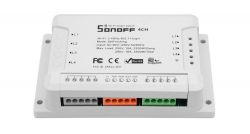
    There are even commercially available 4-channel sonoffs with DIN mounting.

    How to control F&F relays on DIN rail with ESP8266? .
  • #11 18262539
    krzbor
    Level 27  
    khoam wrote:
    To galvanically isolate the 24V relay coil supply voltage from the 3V3 logic.
    Just what for? We short the negatives of the ESP supply (3V) and the 24V supply and connect to the emitter of the transistor. A 1k resistor to the base and then to the ESP, and a relay to the collector, and the other end of the relay to +24V. This is a typical operating circuit (OC) that can cope with different voltages.
  • ADVERTISEMENT
  • #12 18262575
    khoam
    Level 42  
    krzbor wrote:
    This is a typical operating circuit (OC) that handles a variety of voltages.

    As long as the transistor does not fail and there is a 24V breakthrough towards its base and then towards the ESP output pin. The relay coil alone will not be sufficient protection.
    Of course, there are those who claim that they have not used optocouplers in this kind of control circuit for years and nothing bad happens. Let everyone do their own thing.
  • #13 18262619
    krzbor
    Level 27  
    24V relays usually have low currents. You can give a 10k resistor in the base of the transistor instead of 1k. Then, in the event of a breakthrough, we have (24V-3V)/10k =2.1 mA - this is how much will flow through the uP output protection diode. Such a current will not damage it. Nor will it damage the ESP.
  • #14 18262775
    khoam
    Level 42  
    krzbor wrote:
    The 24V relays usually have low currents. You can give a 10k resistor in the base of the transistor instead of 1k. Then in case of a breakthrough we have (24V-3V)/10k =2.1 mA - this is how much will flow through the uP output protection diode. Such a current will not damage it. Nor will it damage the ESP.
    .
    I suggest that the colleague pull up the ESP output with a 10k resistor to 24V. Turn on the circuit for a dozen or so seconds and report the result of these tests.
  • #17 18468086
    shady79
    Level 13  
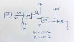
    Hi again so as not to start a similar topic let me ask here on the subject of relay control via esp.
    I have connected the mentioned ESP and actually one of its pins via a PC817 optocoupler to the SSR25DD relay http://www.fotek.com.tw/pdf/SSR-DD.pdf and switching on/off via it the 12V circuit with the LED strip works. On the other hand I have a problem getting dimming via a PWM signal. I have easyesp installed on my esp and when I give e.g. pwm 5.1023 it shines at max but when I give pwm 5.500 it also shines at max a fill of 100 shines say 10% less than at max and a fill of 20 does not shine. It can be concluded that the diodes basically do not react to the changing fill of the pwm signal. What do you think, should I look for the cause from the software side or could this signal be distorted somewhere. There are two optocouplers on the way, the pwm signal is generated by esp at 1kHz as standard.

    How to control F&F relays on DIN rail with ESP8266? .

    I wonder if sometimes this R1 is not too small because it looks like in this case the current is limited to 33mA and the current capacity of the port is 12mA so it would be better to use a resistor in the 330-660ohm range to jerk the current from it to the max
  • ADVERTISEMENT
  • #18 18468953
    tos18
    Level 42  
    These relays have a response time of 1ms so the PWM frequency must be less than 100Hz because the relay will not handle it.
    R2 in my opinion is unnecessary.
    Consider ditching the SSR in favour of a good mosfet and driver - they will certainly be faster.
  • #20 18469034
    shady79
    Level 13  
    And this ssr is not made on a mosfet?
  • #21 18469104
    tos18
    Level 42  
    It probably is - maybe even on two of them. which doesn't change things - a response time of 1ms.
  • #22 18469175
    khoam
    Level 42  
    shady79 wrote:
    And this ssr is not made on a mosfet?
    .
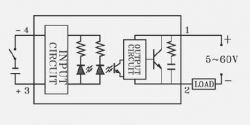
    That much is clear from the manufacturer's note:
    How to control F&F relays on DIN rail with ESP8266? .
    As you have additionally used an external optocoupler at the input, the response time of the circuit has increased.

    Added after 8 [minutes]:

    shady79 wrote:
    the pwm signal is generated by esp at 1kHz as standard
    .
    Reduce to 100Hz (in ESP Easy less will not be set for PWM) and check. By the way you will already observe the LED flicker.
  • #23 18469911
    shady79
    Level 13  
    can the frequency be changed somewhere in the settings or with a command, because I think I read somewhere that you have to change it somewhere in the source file, recompile the program and put it into esp....

    Added after 8 [minutes]:

    shady79 wrote:
    Can the frequency be changed somewhere in the settings or with a command because somewhere I think I read that you have to change it somewhere in the source file, recompile the program and upload it to esp...
    .

    good i think i have found

    PWM,<GPIO>,<duty>,<duration>,<frequency>

    Added after 44 [minutes]:

    I'll check tonight, but just thinking about it, a time of 1ms is 1/1000s so a frequency of 1kHz is theoretically within that range. Maybe it would be enough to give for example 800Hz?

Topic summary

The discussion revolves around controlling DIN rail mounted F&F relays with an ESP8266, which presents challenges due to the relays' 24VDC coil requirements. Users suggest using a transistor to interface the ESP8266's 3.3V output with the relay, as direct control is not feasible. Recommendations include using optocoupler isolation modules and specific transistor configurations to ensure safe operation. Some participants mention alternative solutions like SONOFF modules and Shelly devices, which integrate ESP and relay functionalities. The conversation also touches on PWM control for LED dimming, highlighting the limitations of SSRs and suggesting MOSFETs for better performance.
Summary generated by the language model.
ADVERTISEMENT