logo elektroda
logo elektroda
X
logo elektroda

Extending DS18(B)20 driver - multiple GPIOs and multiple sensors per GPIO

max4elektroda 1641 56
ADVERTISEMENT
📢 Listen (AI):
  • Screenshot of the DS18B20 driver configurator showing a list of detected temperature sensors and their settings.
    As proposed by @p.kaczmarek2 I'll try to share some ideas for my OpenBeken IoT firmware extensions and features here, starting, "as requested" ;-) with the extended DS18(B)20 driver.

    The code is in PR #1627

    I'll start with some information and screenshots, but I would be glad to get some feedback on more basic questions in the later part of this post.

    So, "only" getting the already present driver (/src/driver/ds18b20.c) working wasn't that hard, the most crucial part (timing of the OneWire protocol) was done and improved with many support from others for the "simple" driver. So there only was the driver layer missing, the protocol was working quite good now.

    So the first approach was:
    Move all basic functions into a separate file, so all the basic "one_wire" or "ds18b2" functions (up to read/write a byte) could be shared between the two drivers.

    A bit more challenging were some general decisions: How to handle the sensors?

    A brief excursion:

    All sensors have a unique address that allows them to be addressed on the bus, making it possible to distinguish multiple devices on this bus. The simple driver takes the easy route ;-) It exclusively uses the option, similar to a broadcast in a network, to address "all" devices.

    To read the temperature, the procedure here is: "All devices: Prepare for temperature reading" and then "All devices: Write temperature" – and "all devices" refer to the one sensor on that pin.

    This approach does not work with multiple sensors, at least for reading: If several sensors report their temperature simultaneously, it goes awry.

    Therefore, the addresses of the sensors must be queried individually: "All devices: Prepare for temperature reading" and then "Sensor A: Write temperature," "Sensor B: Write temperature," and so on.


    The driver must first know the addresses of the devices (the sensors). To achieve this, the driver has the ability to determine all sensor addresses using a clever algorithm (for those interested, you can check out https://www.analog.com/en/resources/app-notes/1wire-search-algorithm.html ).

    I have use the following data structure:

     typedef uint8_t DeviceAddress[8]; // wir müssen die Sensoren anhand ihrer Adresse unterscheiden
    
    typedef struct {
      DeviceAddress array[DS18B20MAX];      // unique address of the sensor
      uint8_t index;                        // an index ;-)
      char name[DS18B20MAX][DS18B20namel];  // a description/name for this sensor
      float lasttemp[DS18B20MAX];           // the last temperature read by this sensor
      unsigned short last_read[DS18B20MAX]; // keep track of when the sensor was last read successfully 
      short channel[DS18B20MAX];            // possibly set channel to this temperature value
      short GPIO[DS18B20MAX];               // on which pin is the sensor?
    
    } DS1820devices;


    This also clarifies which features the driver should have, in my opinion:
    - For a single sensor, it doesn't matter, but with multiple sensors, it's worth considering: The sensors should be able to have a "name" assigned, as it's easier for us humans to associate "Kitchen" or "Bedroom" than "28-FF-3C-01-12-34-56-78" or "28-7B-9C-01-23-45-67-89."
    - All information that I previously had only for the entire system is now needed per sensor:
    - On which pin should it be searched for?
     - When did this sensor last respond?
    - Which channel should be used for the temperature?


    So, how does it look like?

    This is the main page after starting the driver with 10 (not configured) DS18B20 clones:
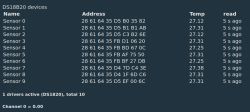
    DS18B20 driver configuration screen showing a list of detected temperature sensors.

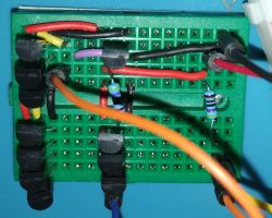
    Maybe you want an idea of how my setup looks like? I made a small "testing breadboard" that will provide two "buses" with 7 and 3 sensors, and one "single" sensor. The 7 and single sensors are meant to be used exclusively; they share the 4.7kΩ resistor (thanks to git user "rpv-tomsk" - see PR PR #1579 - using "HAL_PIN_Setup_Input_Pullup" it might also work without an external pullup).

    Screenshot of the DS18B20 driver configurator showing a list of detected temperature sensors and their settings.

    Now, to configure the sensors, you might use the commands of the driver:

    Obviously you start with

    startDriver DS1820 [seconds between temperature readings]
    start the driver, optional set the interval for reading the sensors, defaults to 15 seconds
    (also present in "simple mode")

    The driver will scan all pins configured as "DS1820_IO" to find the addresses of all sensors.
    You can then configure the sensors with the following commands:

    DS18B20_setsensor <address> <GPIO> <name> [channel]
    Configure sensor address, sensor name and (optional) a channel
    examlpes:
    
          DS18B20_setsensor "0x28 0x01 0x02 0x03 0x04 0x05 0x06 0x07" "5" "kitchen"
          DS18B20_setsensor "0x28 0x02 0x03 0x04 0x05 0x06 0x07 0x08" 5 "bedroom" 3
          DS18B20_setsensor "0x28 0x03 0x04 0x05 0x06 0x07 0x08 0x09" PB21 "my room" 3
    

    If sensor address is "known" (the sensor was found on (initial) scan) pin, name and channel are set/updated
    If sensor is not allready in the list, it will be added, along with pin, name and channel

    This means, we could use the driver even without the (complex) scaning of the bus - it's quite a large function and in best case only needed once: to identify the sensors on the first start.
    Later the addresses are known and could be set directly.


    DS1820_SetResolution <bits> [<sensor address>]
    set the temperature resolution of one / all sensors (if optional address is not present)
    (also present in "simple mode" - only argument is resolution there)
    examples:
     
         DS1820_SetResolution 9 "0x28 0x01 0x02 0x03 0x04 0x05 0x06 0x07"
         DS1820_SetResolution 9


    Important note: for the majority of my (clone) DS18B20 setting the resolution doesn't work, they will alway use 12 bit resolution!

    DS18B20_scansensors
    Clears all data and scans all busses for attached sensors.
    If you added a sensor or not all sensors have been detected, you can start over with a new scan.
    Drawback: you will lose all configured data - but thanks to "setsensor" you can easily add them later again.


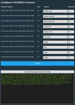
    Since I like it easy, I also added a simple configuration page to do all the settings:
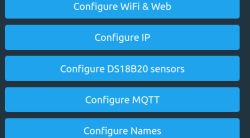
    Screenshot of the DS18B20 driver UI showing a list of detected temperature sensors with names, addresses, pins, and assigned channels.

    Screenshot of the graphical interface for configuring DS18B20 sensors, showing addresses, names, and assigned channels.

    It also allows to generate a "backlog command" of all the configuration. This way, you can easily copy and paste this to autoexec or as a startup command and preserve the settings over a reboot. In my case, the resulting command is:
    
    backlog startDriver DS1820 ; DS18B20_setsensor "0x28 0x61 0x64 0x35 0xD5 0xB0 0x35 0x82"  10 "Kitchen door" 10; DS18B20_setsensor "0x28 0x61 0x64 0x35 0xD5 0xB1 0xB1 0xAB"  10 "Kitchen window" 11; DS18B20_setsensor "0x28 0x61 0x64 0x35 0xD5 0xC3 0xB2 0x6E"  10 "Master Bedroom" 12; DS18B20_setsensor "0x28 0x61 0x64 0x35 0xFB 0xD1 0x06 0x20"  10 "Livingroom " 13; DS18B20_setsensor "0x28 0x61 0x64 0x35 0xFB 0xBD 0x67 0x0C"  10 "Adams room" 14; DS18B20_setsensor "0x28 0x61 0x64 0x35 0xFB 0xAF 0x75 0x50"  10 "Eves room" 15; DS18B20_setsensor "0x28 0x61 0x64 0x35 0xFB 0xBF 0x27 0xDB"  10 "Garage" 16; DS18B20_setsensor "0x28 0x61 0x64 0x35 0xD4 0x7D 0xC4 0x3E"  37 "Pool" 17; DS18B20_setsensor "0x28 0x61 0x64 0x35 0xD4 0x1F 0x6D 0xC6"  37 "Cellar" 18; DS18B20_setsensor "0x28 0x61 0x64 0x35 0xD5 0xEF 0x00 0x6C"  37 "Garden" 19


    The main page will reflect the changes:
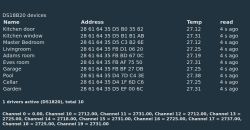
    Screenshot of the DS18B20 driver configuration page showing a list of 10 temperature sensors with names, addresses, and assigned channels.
    you can see the description per sensor and the channels are updated.


    So, I hope this gives a first idea on what I did and how to use the driver.

    You might have noted, the driver is called "DS1820", the commands "DS18B20_XXX" - this is due to the fact that I started with a alternate "full" driver addittionaly to the simple driver (moving some of the simple drivers code to a shared code file).
    rpv-tomsk proposed to use only one file, so I integrated all into one file where a "#define DS1820full 1" will select the full code.

    So, here is my first question to the other developers and supporters: What do you think is "better":

    Having only one code file with "#defines" to select the features?
    + changes made are always made for both versions
    + no need for a separate "ds1820 protocol" file for shared code
    - many "#defines" sometimes make it hard to read the code, might lead to mistakes

    Leaving/switching back to three files: simple, full and shared code?
    + much easier to read, no need to have several "#defines" inside the functions
    - if changes are made, we need to touch two files (if it's in some common code)
    (it's +/- if we also need to change it in two places in one file, if it's inside "#defines")

    Then the big question at the end - do we need this at all?
    Are there many users "waiting" to attach a number of sensors?

    Yes, I made all the afford for this, but there could also be a small solution: Multiple sensors, but with multiple GPIOs, one sensor per pin. No need to struggle with addresses, just looping through all pins with role "DS1820_IO". The channel is already set (together with the pin) and I know that sensor on pin 18 is in the kitchen and the one on pin 21 in the living room.


    So, feel free to give comments in every direction

    Added after 14 [minutes]:

    For a W800, the additional size (simple to full) is about 6k - we have the complex scanning but especially the "nice" configuration GUI will blow the image.

    Cool? Ranking DIY
    About Author
    max4elektroda
    Level 20  
    Offline 
    max4elektroda wrote 479 posts with rating 113, helped 21 times. Been with us since 2024 year.
  • ADVERTISEMENT
  • #2 21585831
    p.kaczmarek2
    Moderator Smart Home
    Thank you for this interesting presentation. The UI idea and naming is very nice, altough I would consider doing it in Web App. Still, since it's already ready...
    My suggestion is to merge it now as-is, but keep it enabled only in OBK-Sensors:
    Extending DS18(B)20 driver - multiple GPIOs and multiple sensors per GPIO

    I prefer single file with #ifdef , it's easier to read and maintain...

    The command generator is nice, but I think newer OBK does not require backlog, you can put each command in next line.
    Helpful post? Buy me a coffee.
  • #3 21585943
    Borygo123
    Level 28  
    If you have your own house and appliances like a cooker etc. then something like this comes in handy. I have temperature readings taken on a WEMOS D1 Mini which sends this to Supli. I have 3 modules connected. On one I have 5 sensors, on the second I have 4 and the third I have a portable one when I want to investigate something. The advantage of this is that I don't have to program anything, just configure the module (i.e. do what a colleague does in the software, but by clicking in the app).
  • #4 21585964
    max4elektroda
    Level 20  
    Thanks for your feedback!
    I understand it's not totally useless ;-)

    @p.kaczmarek2 just a few more questions:
    The multi line command is now available on all platforms?
    If I get it right, the sensor builds are only for Beken platforms?

    I think most users will not need more than one sensor so all the stuff needed for more are kind of an overkill (in the handling and in the GUI - not only the config page but also the main page).
    This would mean, it might be better to have two drivers, simple and full, so you can decide, which one to load.
    That's a new idea, but maybe worth trying?

    Regarding the Web app - good point, but I think I'll first have to figure out how this works.
    Is there some information or tutorial around?
    Do you remember a recent addition I might examine to get an idea?

    Thanks!
  • #5 21586015
    p.kaczmarek2
    Moderator Smart Home
    max4elektroda wrote:

    @p.kaczmarek2 just a few more questions:
    The multi line command is now available on all platforms?

    Well, that's a fair point. Maybe you can then just add a checkbox to choose between formats...
    Multiline command line is treating text as script file so it requires OBK scripting backend enabled, while backlog runs without it and is more lightweight and simple.

    The startup command can be multiline only if ENABLE_OBK_SCRIPTING is enabled in obk_config.h

    max4elektroda wrote:

    If I get it right, the sensor builds are only for Beken platforms?

    Currently yes, but that's not set in stone. It's just that each online build takes time on Github and I'm not sure if we need all permutations. I am also worried that there might be some limit of workflow time on Github and we may hit that eventually.

    Maybe we can add sensors build for other platforms, depending on the requirement, but we still also support just changing obk_config.h and building in PR per user request.


    max4elektroda wrote:

    This would mean, it might be better to have two drivers, simple and full, so you can decide, which one to load.
    That's a new idea, but maybe worth trying?

    I don't have strong opinion on that. The only thing that matters is the flash size on main (simple driver) build. That's because we run into many issues when flash usage is too high, OTA breaks, LFS gets overwritten, etc. I would also suggest to have at least some code in common, maybe common delay defines, etc, at least, it's harder to maintain two separate drivers


    max4elektroda wrote:

    Regarding the Web app - good point, but I think I'll first have to figure out how this works.
    Is there some information or tutorial around?
    Do you remember a recent addition I might examine to get an idea?

    I don't think it's required now, your OBK page done in C is good as well. I think the better priority is getting your other PRs merged, like time improvements, etc.

    Still, if you want to know - tutorial:
    https://www.elektroda.com/news/news3971355.html
    Code:
    https://github.com/OpenBekenIOT/webapp/tree/gh-pages/vue
    Workflow is simple - first add API in rest_interface (OBK style) or json_interface.c (mimics Tasmota), and then use it.

    I also saw you done breaking change to allow time offset in minutes - i can merge it but first can you revert to hours and then just allow fractional parts?
    Helpful post? Buy me a coffee.
  • #6 21586391
    max4elektroda
    Level 20  
    I'll take another deep look on the whole PR. Up to now, I had focus on function: What do we need to get a usable approach.
    I will try to improve it a bit for "size". There might be some debug output, JS is not optimized ...

    p.kaczmarek2 wrote:
    I also saw you done breaking change to allow time offset in minutes - i can merge it but first can you revert to hours and then just allow fractional parts?

    You mean PR #1485?
    Did I understand that right, you want to change the command to be "backward compatible" by not setting the total minutes, but set them e.g. as "0 hour and 30 minutes" like


    CLOCK_CalcDST ..... 1 for one hour
    CLOCK_CalcDST ..... 0:30 for thirty minutes

    ??

    I changed that (reusing the logic from timzone command ....)

    But in the end, this is just to make it almost complete - there seems to be only one location in the world not using one hour offset but 30 minutes, Lord Howe Island in Australia...
  • #7 21586399
    p.kaczmarek2
    Moderator Smart Home
    Flash size matters much in the main build (single DS18B20 version). In sensors build flash size is not top priority, because for sensors build we strip TuyaMCU driver, power metering drivers, etc, LED driver.
    Yes, I can merge it if it's backward compatible, however, I think 1.5 for 1 hour 30 minutes is just fine. No need to parse 0:30.
    Helpful post? Buy me a coffee.
  • #8 21586410
    max4elektroda
    Level 20  
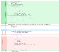
    The code for parsing is already there, I only moved it to a helper function, so it can be used by multiple commands.


    Screenshot of a code snippet in a text editor showing a Python helper function for code parsing.

    I know I might contradict myself (it's very rarely used, so who cares ;-)) but I think 0.5 hours is less user friendly than 0:30 for 30 minutes.
    And we then have a consistent syntax between setting timezone offset and setting DST offset.
  • #9 21586421
    p.kaczmarek2
    Moderator Smart Home
    Hm ok but the question would be how much flash parsing with : consumes. Still, if that's not much, then it's acceptable.
    Helpful post? Buy me a coffee.
  • #10 21586422
    max4elektroda
    Level 20  
    Let me check the size. Will report here.

    I will do the "review" of DS18B20 next week (I hope). Will be quite busy the next time.

    Added after 1 [hours] 9 [minutes]:

    Just checked some file sizes:

    No visible size change for Beken-N -- is it padded?
    W800 is 128 bytes enlarged
    BL602 is 144 bytes enlarged

    This is including the new sanity check for DST offsets > 2h (including an error message, which alone is 93 characters long).

       int off = Tokenizer_GetArgsCount() < 9 ? 60 : hourArg2seconds(8)/60;
       if (off != off%121) {
          ADDLOG_ERROR(LOG_FEATURE_RAW, "CLOCK_CalcDST: DST offset must be <= 2 hours, but is %i minutes. Setting to default of 1 hour",off);
          off=60;
       }


    Two things to remember:
    This feature is off for all platforms (despite simulator - we need it enabled to test)
    As I pointed out earlier: This PR is not high priority or might be ignored for it's use case very low.
    Only the sanity check might be useful, but since we don't check the other arguments ....

    So it's up to you, I really don't mind if this PR is not merged, our discussion (don't get me wrong, I enjoyed it) was longer than the time I spend with the code.
  • ADVERTISEMENT
  • #11 21588290
    p.kaczmarek2
    Moderator Smart Home
    I can merge it, please just point me which PRs are ready.

    This is also good:
    https://github.com/openshwprojects/OpenBK7231T_App/pull/1689
    We could then use this JSON in Web App to use Web App as detailed panel to remove the need of adding more HTML in the firmware.

    @divadiow can you test this PR?
    Helpful post? Buy me a coffee.
  • ADVERTISEMENT
  • #13 21588368
    p.kaczmarek2
    Moderator Smart Home
    Same goes for DS18B20, just give me final confirmation and I'll merge
    Helpful post? Buy me a coffee.
  • #14 21588720
    Tilator
    Level 10  
    B.T.W Is there something odd about DS1820 driver?

    I have two different devices one with BK7231N and the other with ECR6600. I have added this DS1820 sensor them both.

    And both have same trouble. They become very sluggish if the sensor is connected to channel 1. Also the channel reading turns once and while to 0 or 1 depending on FW version while sensor reading still looks something else on HTTP page.

    This does not happen if I configure channel 0 to be used with this sensor. I have not tested any other channels yet, but the strange behavior disappeared and everything works fine when I changed channel 1 to channel 0. Same thing for both devices.

    I have not configured channel 1 to anything else.

    ************************************************************
    A bit more info:

    I have now channel 0 related to DS1820 and channel 2 related to button and relay. Channel 1 is not used at all.

    Still I can see this in log every once and while:

    Info:CMD:tasCmnd POWER (Power1) received with args On
    Info:GEN:No change in channel 1 (still set to 1) - ignoring

    So - is channel 1 hard coded to something?
  • ADVERTISEMENT
  • #15 21588754
    max4elektroda
    Level 20  
    @p.kaczmarek2: I will need some more time: in "simple" mode the driver increases the memory footprint too much. This is mainly because the shared code is more general, e.g. setting resolution will take care about actual setting and only set a changed value. This and some more information or possible debug output increases the size. I'm currently trying to bring this down, but maybe need to rethink how to have two drivers in one.

    Tilator wrote:
    Info:CMD:tasCmnd POWER (Power1) received with args On
    Info:GEN:No change in channel 1 (still set to 1) - ignoring

    tasCmnd is not from DS1820. Looks like some tasmota command?
    Simply try another channel, if 1 is used by tasmota.
  • #16 21588756
    Tilator
    Level 10  
    >>21588754

    I took everything off. Config is empty and autoexec.bat away. I cleared it also by lfs_format.

    But I have a php script on my router running power on/off commands. It really seems to be, it expects relay to be related to channel 1, because using command exec('curl http://x.x.x.x/cm?cmnd=Power1%20On') initiates channel 1 somehow even while relay is configured to use channel 2.

    So - relay has to be configured to channel 1 to make that php command to work?

    I don't use or need MQTT or anything else but setting channel values by php script. Do I need and can I somehow turn tasmota off?

    Or is it simply exec('curl http://x.x.x.x/cm?cmnd=Power2%20On') to use channel 2?

    And answering myself: that's it ;)
  • #17 21588767
    max4elektroda
    Level 20  
    Yes, the 1 in the command refered to channel 1. Good you figured it out by yourself.
  • #18 21590269
    p.kaczmarek2
    Moderator Smart Home
    max4elektroda wrote:
    @p.kaczmarek2: I will need some more time: in "simple" mode the driver increases the memory footprint too much. This is mainly because the shared code is more general, e.g. setting resolution will take care about actual setting and only set a changed value. This and some more information or possible debug output increases the size. I'm currently trying to bring this down, but maybe need to rethink how to have two drivers in one.

    That's a new information. So, since you say so, maybe just keep old driver (separate codebase) as simple one and put the more advanced separately?
    Helpful post? Buy me a coffee.
  • #19 21591096
    max4elektroda
    Level 20  
    Short update: locally (not yet pushed - could not test) I reduced the "overhead" to approx 150 bytes.
    If "every byte counts" in simple driver, I think I should switch back to two drivers - only sharing very basic functions (read/write on onewire bus) since they are already present now in simple driver.
  • #20 21592997
    max4elektroda
    Level 20  
    I tried with two different drivers, only the common code in a file used by both - still 100+ bytes larger. I can only think it's due to the fact that the shared functions will need global symbols, I can't use static functions here as in original code.

    Or am I missing another point, which (slightly) bloats the size?

    https://github.com/MaxineMuster/OpenBK7231T_App/tree/DS18B20_simple%2Bfull
  • #21 21594164
    p.kaczmarek2
    Moderator Smart Home
    Consider that it's just 100 bytes then maybe we can merge it as is... just make sure not to break the existing functionality.

    Multi AHT could also be merged.
    Helpful post? Buy me a coffee.
  • #22 21595460
    max4elektroda
    Level 20  
    Actually I favor to have two separate drivers, opened https://github.com/openshwprojects/OpenBK7231T_App/pull/1705 for this.

    Two differences to the other PR:
    Only changed DS1820 code, not timing for usleep, that should be a separate thread. For me, DS 18B20 on BK7238 don't work, exactly like release version.
    I also made a checkbox to allow multi line commands.

    Now it's only testing of both versions on all platforms and later change obk_config.h to enable full driver only e.g. in sensors release.

    Sadly I don't have any possibly to test, so maybe I can ask @divadiow for support again?

    There are two drivers, the original and DS1820_FULL, both are mutually exclusive.
  • #23 21595464
    divadiow
    Level 34  
    max4elektroda wrote:
    Sadly I don't have any possibly to test, so maybe I can ask @divadiow for support again?


    Sure, but it'll have to be next week I'm afraid. I have no DS18B20 with me.
  • #24 21601042
    divadiow
    Level 34  
    to confirm, the FULL and SIMPLE driver need testing on each (all?) platforms with a single (edit: of course multiple is desired) DS18B20, binaries from this PR https://github.com/openshwprojects/OpenBK7231T_App/pull/1705 ?

    Added after 1 [hours] 17 [minutes]:

    started to try stuff. 1705_merge_8cb2556b9604_4M

    ESP32
    both full and simple cause panic/reboot
    Code: Text
    Log in, to see the code


    it doesn't matter which GPIO is assigned DS1820_IO role or if sensor is connected or not.
    If no pin is assigned role, driver does start.

    Added after 22 [minutes]:

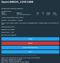
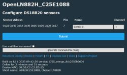
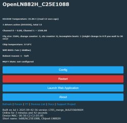
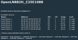
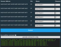
    LN882H - IO A7

    Extending DS18(B)20 driver - multiple GPIOs and multiple sensors per GPIO Extending DS18(B)20 driver - multiple GPIOs and multiple sensors per GPIO Extending DS18(B)20 driver - multiple GPIOs and multiple sensors per GPIO

    Simple ALL log
    Code: Text
    Log in, to see the code


    Full ALL log
    Code: Text
    Log in, to see the code
  • Helpful post
    #26 21601211
    divadiow
    Level 34  
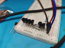
    I thought I should go back and read your first post. I assumed (!) each sensor was to be on its own gpio. I'll remake like your breadboard. Interesting though that with full it will detect the first two but never the last of the 3 I have set, whatever gpio above the second one.

    Anyway, I'll change it up.

    Extending DS18(B)20 driver - multiple GPIOs and multiple sensors per GPIO

    Added after 33 [minutes]:

    Extending DS18(B)20 driver - multiple GPIOs and multiple sensors per GPIO Extending DS18(B)20 driver - multiple GPIOs and multiple sensors per GPIO

    Spoiler:
    Info:SENSOR:DS1820 - Sensor 0x28 0xA6 0xB2 0x55 0x00 0x00 0x00 0x65 on B3 reported 26.19
    Debug:SENSOR:DS1820 - Found device at index 2 - GPIO=19
    Debug:SENSOR:DS1820 - GPIO found for device - DS18B20_GPIO=19
    Debug:SENSOR:DS1820 - Found device at index 2 - GPIO=19
    Debug:SENSOR:DS1820 - ds18b20_readScratchPad returned 1 - Crc8CQuick=121 / scratchPad[SCRATCHPAD_CRC]=121
    Debug:SENSOR:DS1820 - ds18b20_Scratchpat2TempC: family=28, raw=3376 (12 bit resolution)
    Debug:SENSOR:DS1820 - Device 2 (0x28 0x5E 0x34 0x59 0x00 0x00 0x00 0xF3) reported 26.38
    Info:SENSOR:DS1820 - Sensor 0x28 0x5E 0x34 0x59 0x00 0x00 0x00 0xF3 on B3 reported 26.38
    Debug:SENSOR:DS1820 - Found device at index 3 - GPIO=19
    Debug:SENSOR:DS1820 - GPIO found for device - DS18B20_GPIO=19
    Debug:SENSOR:DS1820 - Found device at index 3 - GPIO=19
    Debug:SENSOR:DS1820 - ds18b20_readScratchPad returned 1 - Crc8CQuick=121 / scratchPad[SCRATCHPAD_CRC]=121
    Debug:SENSOR:DS1820 - ds18b20_Scratchpat2TempC: family=28, raw=3376 (12 bit resolution)
    Debug:SENSOR:DS1820 - Device 3 (0x28 0xF9 0x28 0x5A 0x00 0x00 0x00 0xFF) reported 26.38
    Info:SENSOR:DS1820 - Sensor 0x28 0xF9 0x28 0x5A 0x00 0x00 0x00 0xFF on B3 reported 26.38
    Debug:SENSOR:DS1820 - Found device at index 4 - GPIO=19
    Debug:SENSOR:DS1820 - GPIO found for device - DS18B20_GPIO=19
    Debug:SENSOR:DS1820 - Found device at index 4 - GPIO=19
    Debug:SENSOR:DS1820 - ds18b20_readScratchPad returned 1 - Crc8CQuick=85 / scratchPad[SCRATCHPAD_CRC]=85
    Debug:SENSOR:DS1820 - ds18b20_Scratchpat2TempC: family=28, raw=3360 (12 bit resolution)
    Debug:SENSOR:DS1820 - Device 4 (0x28 0xFD 0xAB 0x55 0x00 0x00 0x00 0x3C) reported 26.25
    Info:SENSOR:DS1820 - Sensor 0x28 0xFD 0xAB 0x55 0x00 0x00 0x00 0x3C on B3 reported 26.25
    Debug:SENSOR:DS1820 - Found device at index 5 - GPIO=19
    Debug:SENSOR:DS1820 - GPIO found for device - DS18B20_GPIO=19
    Debug:SENSOR:DS1820 - Found device at index 5 - GPIO=19
    Debug:SENSOR:DS1820 - ds18b20_readScratchPad returned 1 - Crc8CQuick=65 / scratchPad[SCRATCHPAD_CRC]=65
    Debug:SENSOR:DS1820 - ds18b20_Scratchpat2TempC: family=28, raw=3352 (12 bit resolution)
    Debug:SENSOR:DS1820 - Device 5 (0x28 0x33 0x03 0x57 0x00 0x00 0x00 0xBA) reported 26.19
    Info:SENSOR:DS1820 - Sensor 0x28 0x33 0x03 0x57 0x00 0x00 0x00 0xBA on B3 reported 26.19
    Debug:SENSOR:DS1820 - .. Pin 19 found! dsread=0
    Info:SENSOR:DS1820 - Starting conversion
    Debug:SENSOR:DS1820 - .. Pin 19 found! dsread=1
    Info:SENSOR:DS1820 - Reading temperature from 6 DS18B20 sensor(s)
    Debug:SENSOR:DS1820 - Found device at index 0 - GPIO=19
    Debug:SENSOR:DS1820 - GPIO found for device - DS18B20_GPIO=19
    Debug:SENSOR:DS1820 - Found device at index 0 - GPIO=19
    Debug:SENSOR:DS1820 - ds18b20_readScratchPad returned 1 - Crc8CQuick=87 / scratchPad[SCRATCHPAD_CRC]=87
    Debug:SENSOR:DS1820 - ds18b20_Scratchpat2TempC: family=28, raw=3344 (12 bit resolution)
    Debug:SENSOR:DS1820 - Device 0 (0x28 0x44 0x02 0x5B 0x00 0x00 0x00 0x78) reported 26.12
    Info:SENSOR:DS1820 - Sensor 0x28 0x44 0x02 0x5B 0x00 0x00 0x00 0x78 on B3 reported 26.12
    Debug:SENSOR:DS1820 - Found device at index 1 - GPIO=19
    Debug:SENSOR:DS1820 - GPIO found for device - DS18B20_GPIO=19
    Debug:SENSOR:DS1820 - Found device at index 1 - GPIO=19
    Debug:SENSOR:DS1820 - ds18b20_readScratchPad returned 1 - Crc8CQuick=65 / scratchPad[SCRATCHPAD_CRC]=65
    Debug:SENSOR:DS1820 - ds18b20_Scratchpat2TempC: family=28, raw=3352 (12 bit resolution)
    Debug:SENSOR:DS1820 - Device 1 (0x28 0xA6 0xB2 0x55 0x00 0x00 0x00 0x65) reported 26.19
    Info:SENSOR:DS1820 - Sensor 0x28 0xA6 0xB2 0x55 0x00 0x00 0x00 0x65 on B3 reported 26.19
    Debug:SENSOR:DS1820 - Found device at index 2 - GPIO=19
    Debug:SENSOR:DS1820 - GPIO found for device - DS18B20_GPIO=19
    Debug:SENSOR:DS1820 - Found device at index 2 - GPIO=19
    Debug:SENSOR:DS1820 - ds18b20_readScratchPad returned 1 - Crc8CQuick=120 / scratchPad[SCRATCHPAD_CRC]=120
    Debug:SENSOR:DS1820 - ds18b20_Scratchpat2TempC: family=28, raw=3368 (12 bit resolution)
    Debug:SENSOR:DS1820 - Device 2 (0x28 0x5E 0x34 0x59 0x00 0x00 0x00 0xF3) reported 26.31
    Info:SENSOR:DS1820 - Sensor 0x28 0x5E 0x34 0x59 0x00 0x00 0x00 0xF3 on B3 reported 26.31
    Debug:SENSOR:DS1820 - Found device at index 3 - GPIO=19
    Debug:SENSOR:DS1820 - GPIO found for device - DS18B20_GPIO=19
    Debug:SENSOR:DS1820 - Found device at index 3 - GPIO=19
    Debug:SENSOR:DS1820 - ds18b20_readScratchPad returned 1 - Crc8CQuick=121 / scratchPad[SCRATCHPAD_CRC]=121
    Debug:SENSOR:DS1820 - ds18b20_Scratchpat2TempC: family=28, raw=3376 (12 bit resolution)
    Debug:SENSOR:DS1820 - Device 3 (0x28 0xF9 0x28 0x5A 0x00 0x00 0x00 0xFF) reported 26.38
    Info:SENSOR:DS1820 - Sensor 0x28 0xF9 0x28 0x5A 0x00 0x00 0x00 0xFF on B3 reported 26.38
    Debug:SENSOR:DS1820 - Found device at index 4 - GPIO=19
    Debug:SENSOR:DS1820 - GPIO found for device - DS18B20_GPIO=19
    Debug:SENSOR:DS1820 - Found device at index 4 - GPIO=19
    Debug:SENSOR:DS1820 - ds18b20_readScratchPad returned 1 - Crc8CQuick=120 / scratchPad[SCRATCHPAD_CRC]=120
    Debug:SENSOR:DS1820 - ds18b20_Scratchpat2TempC: family=28, raw=3368 (12 bit resolution)
    Debug:SENSOR:DS1820 - Device 4 (0x28 0xFD 0xAB 0x55 0x00 0x00 0x00 0x3C) reported 26.31
    Info:SENSOR:DS1820 - Sensor 0x28 0xFD 0xAB 0x55 0x00 0x00 0x00 0x3C on B3 reported 26.31
    Debug:SENSOR:DS1820 - Found device at index 5 - GPIO=19
    Debug:SENSOR:DS1820 - GPIO found for device - DS18B20_GPIO=19
    Debug:SENSOR:DS1820 - Found device at index 5 - GPIO=19
    Debug:SENSOR:DS1820 - ds18b20_readScratchPad returned 1 - Crc8CQuick=65 / scratchPad[SCRATCHPAD_CRC]=65
    Debug:SENSOR:DS1820 - ds18b20_Scratchpat2TempC: family=28, raw=3352 (12 bit resolution)
    Debug:SENSOR:DS1820 - Device 5 (0x28 0x33 0x03 0x57 0x00 0x00 0x00 0xBA) reported 26.19
    Info:SENSOR:DS1820 - Sensor 0x28 0x33 0x03 0x57 0x00 0x00 0x00 0xBA on B3 reported 26.19
    Debug:SENSOR:DS1820 - .. Pin 19 found! dsread=0
    Info:SENSOR:DS1820 - Starting conversion
    Debug:SENSOR:DS1820 - .. Pin 19 found! dsread=1
    Info:SENSOR:DS1820 - Reading temperature from 6 DS18B20 sensor(s)
    Debug:SENSOR:DS1820 - Found device at index 0 - GPIO=19
    Debug:SENSOR:DS1820 - GPIO found for device - DS18B20_GPIO=19
    Debug:SENSOR:DS1820 - Found device at index 0 - GPIO=19
    Debug:SENSOR:DS1820 - ds18b20_readScratchPad returned 1 - Crc8CQuick=86 / scratchPad[SCRATCHPAD_CRC]=86
    Debug:SENSOR:DS1820 - ds18b20_Scratchpat2TempC: family=28, raw=3336 (12 bit resolution)
    Debug:SENSOR:DS1820 - Device 0 (0x28 0x44 0x02 0x5B 0x00 0x00 0x00 0x78) reported 26.06
    Info:SENSOR:DS1820 - Sensor 0x28 0x44 0x02 0x5B 0x00 0x00 0x00 0x78 on B3 reported 26.06
    Debug:SENSOR:DS1820 - Found device at index 1 - GPIO=19
    Debug:SENSOR:DS1820 - GPIO found for device - DS18B20_GPIO=19
    Debug:SENSOR:DS1820 - Found device at index 1 - GPIO=19
    Debug:SENSOR:DS1820 - ds18b20_readScratchPad returned 1 - Crc8CQuick=65 / scratchPad[SCRATCHPAD_CRC]=65
    Debug:SENSOR:DS1820 - ds18b20_Scratchpat2TempC: family=28, raw=3352 (12 bit resolution)
    Debug:SENSOR:DS1820 - Device 1 (0x28 0xA6 0xB2 0x55 0x00 0x00 0x00 0x65) reported 26.19
    Info:SENSOR:DS1820 - Sensor 0x28 0xA6 0xB2 0x55 0x00 0x00 0x00 0x65 on B3 reported 26.19
    Debug:SENSOR:DS1820 - Found device at index 2 - GPIO=19
    Debug:SENSOR:DS1820 - GPIO found for device - DS18B20_GPIO=19
    Debug:SENSOR:DS1820 - Found device at index 2 - GPIO=19
    Debug:SENSOR:DS1820 - ds18b20_readScratchPad returned 1 - Crc8CQuick=121 / scratchPad[SCRATCHPAD_CRC]=121
    Debug:SENSOR:DS1820 - ds18b20_Scratchpat2TempC: family=28, raw=3376 (12 bit resolution)
    Debug:SENSOR:DS1820 - Device 2 (0x28 0x5E 0x34 0x59 0x00 0x00 0x00 0xF3) reported 26.38
    Info:SENSOR:DS1820 - Sensor 0x28 0x5E 0x34 0x59 0x00 0x00 0x00 0xF3 on B3 reported 26.38
    Debug:SENSOR:DS1820 - Found device at index 3 - GPIO=19
    Debug:SENSOR:DS1820 - GPIO found for device - DS18B20_GPIO=19
    Debug:SENSOR:DS1820 - Found device at index 3 - GPIO=19
    Debug:SENSOR:DS1820 - ds18b20_readScratchPad returned 1 - Crc8CQuick=121 / scratchPad[SCRATCHPAD_CRC]=121
    Debug:SENSOR:DS1820 - ds18b20_Scratchpat2TempC: family=28, raw=3376 (12 bit resolution)
    Debug:SENSOR:DS1820 - Device 3 (0x28 0xF9 0x28 0x5A 0x00 0x00 0x00 0xFF) reported 26.38
    Info:SENSOR:DS1820 - Sensor 0x28 0xF9 0x28 0x5A 0x00 0x00 0x00 0xFF on B3 reported 26.38
    Debug:SENSOR:DS1820 - Found device at index 4 - GPIO=19
    Debug:SENSOR:DS1820 - GPIO found for device - DS18B20_GPIO=19
    Debug:SENSOR:DS1820 - Found device at index 4 - GPIO=19
    Debug:SENSOR:DS1820 - ds18b20_readScratchPad returned 1 - Crc8CQuick=85 / scratchPad[SCRATCHPAD_CRC]=85
    Debug:SENSOR:DS1820 - ds18b20_Scratchpat2TempC: family=28, raw=3360 (12 bit resolution)
    Debug:SENSOR:DS1820 - Device 4 (0x28 0xFD 0xAB 0x55 0x00 0x00 0x00 0x3C) reported 26.25
    Info:SENSOR:DS1820 - Sensor 0x28 0xFD 0xAB 0x55 0x00 0x00 0x00 0x3C on B3 reported 26.25
    Debug:SENSOR:DS1820 - Found device at index 5 - GPIO=19
    Debug:SENSOR:DS1820 - GPIO found for device - DS18B20_GPIO=19
    Debug:SENSOR:DS1820 - Found device at index 5 - GPIO=19
    Debug:SENSOR:DS1820 - ds18b20_readScratchPad returned 1 - Crc8CQuick=65 / scratchPad[SCRATCHPAD_CRC]=65
    Debug:SENSOR:DS1820 - ds18b20_Scratchpat2TempC: family=28, raw=3352 (12 bit resolution)
    Debug:SENSOR:DS1820 - Device 5 (0x28 0x33 0x03 0x57 0x00 0x00 0x00 0xBA) reported 26.19
    Info:SENSOR:DS1820 - Sensor 0x28 0x33 0x03 0x57 0x00 0x00 0x00 0xBA on B3 reported 26.19
    Debug:SENSOR:DS1820 - .. Pin 19 found! dsread=0
    Info:SENSOR:DS1820 - Starting conversion
    Debug:SENSOR:DS1820 - .. Pin 19 found! dsread=1
    Info:SENSOR:DS1820 - Reading temperature from 6 DS18B20 sensor(s)
    Debug:SENSOR:DS1820 - Found device at index 0 - GPIO=19
    Debug:SENSOR:DS1820 - GPIO found for device - DS18B20_GPIO=19
    Debug:SENSOR:DS1820 - Found device at index 0 - GPIO=19
    Debug:SENSOR:DS1820 - ds18b20_readScratchPad returned 1 - Crc8CQuick=87 / scratchPad[SCRATCHPAD_CRC]=87
    Debug:SENSOR:DS1820 - ds18b20_Scratchpat2TempC: family=28, raw=3344 (12 bit resolution)
    Debug:SENSOR:DS1820 - Device 0 (0x28 0x44 0x02 0x5B 0x00 0x00 0x00 0x78) reported 26.12
    Info:SENSOR:DS1820 - Sensor 0x28 0x44 0x02 0x5B 0x00 0x00 0x00 0x78 on B3 reported 26.12
    Debug:SENSOR:DS1820 - Found device at index 1 - GPIO=19
    Debug:SENSOR:DS1820 - GPIO found for device - DS18B20_GPIO=19
    Debug:SENSOR:DS1820 - Found device at index 1 - GPIO=19
    Debug:SENSOR:DS1820 - ds18b20_readScratchPad returned 1 - Crc8CQuick=65 / scratchPad[SCRATCHPAD_CRC]=65
    Debug:SENSOR:DS1820 - ds18b20_Scratchpat2TempC: family=28, raw=3352 (12 bit resolution)
    Debug:SENSOR:DS1820 - Device 1 (0x28 0xA6 0xB2 0x55 0x00 0x00 0x00 0x65) reported 26.19
    Info:SENSOR:DS1820 - Sensor 0x28 0xA6 0xB2 0x55 0x00 0x00 0x00 0x65 on B3 reported 26.19
    Debug:SENSOR:DS1820 - Found device at index 2 - GPIO=19
    Debug:SENSOR:DS1820 - GPIO found for device - DS18B20_GPIO=19
    Debug:SENSOR:DS1820 - Found device at index 2 - GPIO=19
    Debug:SENSOR:DS1820 - ds18b20_readScratchPad returned 1 - Crc8CQuick=121 / scratchPad[SCRATCHPAD_CRC]=121
    Debug:SENSOR:DS1820 - ds18b20_Scratchpat2TempC: family=28, raw=3376 (12 bit resolution)
    Debug:SENSOR:DS1820 - Device 2 (0x28 0x5E 0x34 0x59 0x00 0x00 0x00 0xF3) reported 26.38
    Info:SENSOR:DS1820 - Sensor 0x28 0x5E 0x34 0x59 0x00 0x00 0x00 0xF3 on B3 reported 26.38
    Debug:SENSOR:DS1820 - Found device at index 3 - GPIO=19
    Debug:SENSOR:DS1820 - GPIO found for device - DS18B20_GPIO=19
    Debug:SENSOR:DS1820 - Found device at index 3 - GPIO=19
    Debug:SENSOR:DS1820 - ds18b20_readScratchPad returned 1 - Crc8CQuick=121 / scratchPad[SCRATCHPAD_CRC]=121
    Debug:SENSOR:DS1820 - ds18b20_Scratchpat2TempC: family=28, raw=3376 (12 bit resolution)
    Debug:SENSOR:DS1820 - Device 3 (0x28 0xF9 0x28 0x5A 0x00 0x00 0x00 0xFF) reported 26.38
    Info:SENSOR:DS1820 - Sensor 0x28 0xF9 0x28 0x5A 0x00 0x00 0x00 0xFF on B3 reported 26.38
    Debug:SENSOR:DS1820 - Found device at index 4 - GPIO=19
    Debug:SENSOR:DS1820 - GPIO found for device - DS18B20_GPIO=19
    Debug:SENSOR:DS1820 - Found device at index 4 - GPIO=19
    Debug:SENSOR:DS1820 - ds18b20_readScratchPad returned 1 - Crc8CQuick=85 / scratchPad[SCRATCHPAD_CRC]=85
    Debug:SENSOR:DS1820 - ds18b20_Scratchpat2TempC: family=28, raw=3360 (12 bit resolution)
    Debug:SENSOR:DS1820 - Device 4 (0x28 0xFD 0xAB 0x55 0x00 0x00 0x00 0x3C) reported 26.25
    Info:SENSOR:DS1820 - Sensor 0x28 0xFD 0xAB 0x55 0x00 0x00 0x00 0x3C on B3 reported 26.25
    Debug:SENSOR:DS1820 - Found device at index 5 - GPIO=19
    Debug:SENSOR:DS1820 - GPIO found for device - DS18B20_GPIO=19
    Debug:SENSOR:DS1820 - Found device at index 5 - GPIO=19
    Debug:SENSOR:DS1820 - ds18b20_readScratchPad returned 1 - Crc8CQuick=65 / scratchPad[SCRATCHPAD_CRC]=65
    Debug:SENSOR:DS1820 - ds18b20_Scratchpat2TempC: family=28, raw=3352 (12 bit resolution)
    Debug:SENSOR:DS1820 - Device 5 (0x28 0x33 0x03 0x57 0x00 0x00 0x00 0xBA) reported 26.19
    Info:SENSOR:DS1820 - Sensor 0x28 0x33 0x03 0x57 0x00 0x00 0x00 0xBA on B3 reported 26.19
    Debug:SENSOR:DS1820 - .. Pin 19 found! dsread=0
    Info:SENSOR:DS1820 - Starting conversion
    Debug:SENSOR:DS1820 - .. Pin 19 found! dsread=1
    Info:SENSOR:DS1820 - Reading temperature from 6 DS18B20 sensor(s)
    Debug:SENSOR:DS1820 - Found device at index 0 - GPIO=19
    Debug:SENSOR:DS1820 - GPIO found for device - DS18B20_GPIO=19
    Debug:SENSOR:DS1820 - Found device at index 0 - GPIO=19
    Debug:SENSOR:DS1820 - ds18b20_readScratchPad returned 1 - Crc8CQuick=86 / scratchPad[SCRATCHPAD_CRC]=86
    Debug:SENSOR:DS1820 - ds18b20_Scratchpat2TempC: family=28, raw=3336 (12 bit resolution)
    Debug:SENSOR:DS1820 - Device 0 (0x28 0x44 0x02 0x5B 0x00 0x00 0x00 0x78) reported 26.06
    Info:SENSOR:DS1820 - Sensor 0x28 0x44 0x02 0x5B 0x00 0x00 0x00 0x78 on B3 reported 26.06
    Debug:SENSOR:DS1820 - Found device at index 1 - GPIO=19
    Debug:SENSOR:DS1820 - GPIO found for device - DS18B20_GPIO=19
    Debug:SENSOR:DS1820 - Found device at index 1 - GPIO=19
    Debug:SENSOR:DS1820 - ds18b20_readScratchPad returned 1 - Crc8CQuick=65 / scratchPad[SCRATCHPAD_CRC]=65
    Debug:SENSOR:DS1820 - ds18b20_Scratchpat2TempC: family=28, raw=3352 (12 bit resolution)
    Debug:SENSOR:DS1820 - Device 1 (0x28 0xA6 0xB2 0x55 0x00 0x00 0x00 0x65) reported 26.19
    Info:SENSOR:DS1820 - Sensor 0x28 0xA6 0xB2 0x55 0x00 0x00 0x00 0x65 on B3 reported 26.19
    Debug:SENSOR:DS1820 - Found device at index 2 - GPIO=19
    Debug:SENSOR:DS1820 - GPIO found for device - DS18B20_GPIO=19
    Debug:SENSOR:DS1820 - Found device at index 2 - GPIO=19
    Debug:SENSOR:DS1820 - ds18b20_readScratchPad returned 1 - Crc8CQuick=121 / scratchPad[SCRATCHPAD_CRC]=121
    Debug:SENSOR:DS1820 - ds18b20_Scratchpat2TempC: family=28, raw=3376 (12 bit resolution)
    Debug:SENSOR:DS1820 - Device 2 (0x28 0x5E 0x34 0x59 0x00 0x00 0x00 0xF3) reported 26.38
    Info:SENSOR:DS1820 - Sensor 0x28 0x5E 0x34 0x59 0x00 0x00 0x00 0xF3 on B3 reported 26.38
    Debug:SENSOR:DS1820 - Found device at index 3 - GPIO=19
    Debug:SENSOR:DS1820 - GPIO found for device - DS18B20_GPIO=19
    Debug:SENSOR:DS1820 - Found device at index 3 - GPIO=19
    Debug:SENSOR:DS1820 - ds18b20_readScratchPad returned 1 - Crc8CQuick=121 / scratchPad[SCRATCHPAD_CRC]=121
    Debug:SENSOR:DS1820 - ds18b20_Scratchpat2TempC: family=28, raw=3376 (12 bit resolution)
    Debug:SENSOR:DS1820 - Device 3 (0x28 0xF9 0x28 0x5A 0x00 0x00 0x00 0xFF) reported 26.38
    Info:SENSOR:DS1820 - Sensor 0x28 0xF9 0x28 0x5A 0x00 0x00 0x00 0xFF on B3 reported 26.38
    Debug:SENSOR:DS1820 - Found device at index 4 - GPIO=19
    Debug:SENSOR:DS1820 - GPIO found for device - DS18B20_GPIO=19
    Debug:SENSOR:DS1820 - Found device at index 4 - GPIO=19
    Debug:SENSOR:DS1820 - ds18b20_readScratchPad returned 1 - Crc8CQuick=85 / scratchPad[SCRATCHPAD_CRC]=85
    Debug:SENSOR:DS1820 - ds18b20_Scratchpat2TempC: family=28, raw=3360 (12 bit resolution)
    Debug:SENSOR:DS1820 - Device 4 (0x28 0xFD 0xAB 0x55 0x00 0x00 0x00 0x3C) reported 26.25
    Info:SENSOR:DS1820 - Sensor 0x28 0xFD 0xAB 0x55 0x00 0x00 0x00 0x3C on B3 reported 26.25
    Debug:SENSOR:DS1820 - Found device at index 5 - GPIO=19
    Debug:SENSOR:DS1820 - GPIO found for device - DS18B20_GPIO=19
    Debug:SENSOR:DS1820 - Found device at index 5 - GPIO=19
    Debug:SENSOR:DS1820 - ds18b20_readScratchPad returned 1 - Crc8CQuick=65 / scratchPad[SCRATCHPAD_CRC]=65
    Debug:SENSOR:DS1820 - ds18b20_Scratchpat2TempC: family=28, raw=3352 (12 bit resolution)
    Debug:SENSOR:DS1820 - Device 5 (0x28 0x33 0x03 0x57 0x00 0x00 0x00 0xBA) reported 26.19
    Info:SENSOR:DS1820 - Sensor 0x28 0x33 0x03 0x57 0x00 0x00 0x00 0xBA on B3 reported 26.19
    Debug:SENSOR:DS1820 - .. Pin 19 found! dsread=0
    Info:SENSOR:DS1820 - Starting conversion
    Debug:SENSOR:DS1820 - .. Pin 19 found! dsread=1
    Info:SENSOR:DS1820 - Reading temperature from 6 DS18B20 sensor(s)
    Debug:SENSOR:DS1820 - Found device at index 0 - GPIO=19
    Debug:SENSOR:DS1820 - GPIO found for device - DS18B20_GPIO=19
    Debug:SENSOR:DS1820 - Found device at index 0 - GPIO=19
    Debug:SENSOR:DS1820 - ds18b20_readScratchPad returned 1 - Crc8CQuick=225 / scratchPad[SCRATCHPAD_CRC]=225
    Debug:SENSOR:DS1820 - ds18b20_Scratchpat2TempC: family=28, raw=3328 (12 bit resolution)
    Debug:SENSOR:DS1820 - Device 0 (0x28 0x44 0x02 0x5B 0x00 0x00 0x00 0x78) reported 26.00
    Info:SENSOR:DS1820 - Sensor 0x28 0x44 0x02 0x5B 0x00 0x00 0x00 0x78 on B3 reported 26.00
    Debug:SENSOR:DS1820 - Found device at index 1 - GPIO=19
    Debug:SENSOR:DS1820 - GPIO found for device - DS18B20_GPIO=19
    Debug:SENSOR:DS1820 - Found device at index 1 - GPIO=19
    Debug:SENSOR:DS1820 - ds18b20_readScratchPad returned 1 - Crc8CQuick=65 / scratchPad[SCRATCHPAD_CRC]=65
    Debug:SENSOR:DS1820 - ds18b20_Scratchpat2TempC: family=28, raw=3352 (12 bit resolution)
    Debug:SENSOR:DS1820 - Device 1 (0x28 0xA6 0xB2 0x55 0x00 0x00 0x00 0x65) reported 26.19
    Info:SENSOR:DS1820 - Sensor 0x28 0xA6 0xB2 0x55 0x00 0x00 0x00 0x65 on B3 reported 26.19
    Debug:SENSOR:DS1820 - Found device at index 2 - GPIO=19
    Debug:SENSOR:DS1820 - GPIO found for device - DS18B20_GPIO=19
    Debug:SENSOR:DS1820 - Found device at index 2 - GPIO=19
    Debug:SENSOR:DS1820 - ds18b20_readScratchPad returned 1 - Crc8CQuick=121 / scratchPad[SCRATCHPAD_CRC]=121
    Debug:SENSOR:DS1820 - ds18b20_Scratchpat2TempC: family=28, raw=3376 (12 bit resolution)
    Debug:SENSOR:DS1820 - Device 2 (0x28 0x5E 0x34 0x59 0x00 0x00 0x00 0xF3) reported 26.38
    Info:SENSOR:DS1820 - Sensor 0x28 0x5E 0x34 0x59 0x00 0x00 0x00 0xF3 on B3 reported 26.38
    Debug:SENSOR:DS1820 - Found device at index 3 - GPIO=19
    Debug:SENSOR:DS1820 - GPIO found for device - DS18B20_GPIO=19
    Debug:SENSOR:DS1820 - Found device at index 3 - GPIO=19
    Debug:SENSOR:DS1820 - ds18b20_readScratchPad returned 1 - Crc8CQuick=120 / scratchPad[SCRATCHPAD_CRC]=120
    Debug:SENSOR:DS1820 - ds18b20_Scratchpat2TempC: family=28, raw=3368 (12 bit resolution)
    Debug:SENSOR:DS1820 - Device 3 (0x28 0xF9 0x28 0x5A 0x00 0x00 0x00 0xFF) reported 26.31
    Info:SENSOR:DS1820 - Sensor 0x28 0xF9 0x28 0x5A 0x00 0x00 0x00 0xFF on B3 reported 26.31
    Debug:SENSOR:DS1820 - Found device at index 4 - GPIO=19
    Debug:SENSOR:DS1820 - GPIO found for device - DS18B20_GPIO=19
    Debug:SENSOR:DS1820 - Found device at index 4 - GPIO=19
    Debug:SENSOR:DS1820 - ds18b20_readScratchPad returned 1 - Crc8CQuick=85 / scratchPad[SCRATCHPAD_CRC]=85
    Debug:SENSOR:DS1820 - ds18b20_Scratchpat2TempC: family=28, raw=3360 (12 bit resolution)
    Debug:SENSOR:DS1820 - Device 4 (0x28 0xFD 0xAB 0x55 0x00 0x00 0x00 0x3C) reported 26.25
    Info:SENSOR:DS1820 - Sensor 0x28 0xFD 0xAB 0x55 0x00 0x00 0x00 0x3C on B3 reported 26.25
    Debug:SENSOR:DS1820 - Found device at index 5 - GPIO=19
    Debug:SENSOR:DS1820 - GPIO found for device - DS18B20_GPIO=19
    Debug:SENSOR:DS1820 - Found device at index 5 - GPIO=19
    Debug:SENSOR:DS1820 - ds18b20_readScratchPad returned 1 - Crc8CQuick=85 / scratchPad[SCRATCHPAD_CRC]=85
    Debug:SENSOR:DS1820 - ds18b20_Scratchpat2TempC: family=28, raw=3360 (12 bit resolution)
    Debug:SENSOR:DS1820 - Device 5 (0x28 0x33 0x03 0x57 0x00 0x00 0x00 0xBA) reported 26.25
    Info:SENSOR:DS1820 - Sensor 0x28 0x33 0x03 0x57 0x00 0x00 0x00 0xBA on B3 reported 26.25
    Debug:SENSOR:DS1820 - .. Pin 19 found! dsread=0
    Info:SENSOR:DS1820 - Starting conversion
    Debug:SENSOR:DS1820 - .. Pin 19 found! dsread=1
    Info:SENSOR:DS1820 - Reading temperature from 6 DS18B20 sensor(s)
    Debug:SENSOR:DS1820 - Found device at index 0 - GPIO=19
    Debug:SENSOR:DS1820 - GPIO found for device - DS18B20_GPIO=19
    Debug:SENSOR:DS1820 - Found device at index 0 - GPIO=19
    Debug:SENSOR:DS1820 - ds18b20_readScratchPad returned 1 - Crc8CQuick=86 / scratchPad[SCRATCHPAD_CRC]=86
    Debug:SENSOR:DS1820 - ds18b20_Scratchpat2TempC: family=28, raw=3336 (12 bit resolution)
    Debug:SENSOR:DS1820 - Device 0 (0x28 0x44 0x02 0x5B 0x00 0x00 0x00 0x78) reported 26.06
    Info:SENSOR:DS1820 - Sensor 0x28 0x44 0x02 0x5B 0x00 0x00 0x00 0x78 on B3 reported 26.06
    Debug:SENSOR:DS1820 - Found device at index 1 - GPIO=19
    Debug:SENSOR:DS1820 - GPIO found for device - DS18B20_GPIO=19
    Debug:SENSOR:DS1820 - Found device at index 1 - GPIO=19
    Debug:SENSOR:DS1820 - ds18b20_readScratchPad returned 1 - Crc8CQuick=87 / scratchPad[SCRATCHPAD_CRC]=87
    Debug:SENSOR:DS1820 - ds18b20_Scratchpat2TempC: family=28, raw=3344 (12 bit resolution)
    Debug:SENSOR:DS1820 - Device 1 (0x28 0xA6 0xB2 0x55 0x00 0x00 0x00 0x65) reported 26.12
    Info:SENSOR:DS1820 - Sensor 0x28 0xA6 0xB2 0x55 0x00 0x00 0x00 0x65 on B3 reported 26.12
    Debug:SENSOR:DS1820 - Found device at index 2 - GPIO=19
    Debug:SENSOR:DS1820 - GPIO found for device - DS18B20_GPIO=19
    Debug:SENSOR:DS1820 - Found device at index 2 - GPIO=19
    Debug:SENSOR:DS1820 - ds18b20_readScratchPad returned 1 - Crc8CQuick=120 / scratchPad[SCRATCHPAD_CRC]=120
    Debug:SENSOR:DS1820 - ds18b20_Scratchpat2TempC: family=28, raw=3368 (12 bit resolution)
    Debug:SENSOR:DS1820 - Device 2 (0x28 0x5E 0x34 0x59 0x00 0x00 0x00 0xF3) reported 26.31
    Info:SENSOR:DS1820 - Sensor 0x28 0x5E 0x34 0x59 0x00 0x00 0x00 0xF3 on B3 reported 26.31
    Debug:SENSOR:DS1820 - Found device at index 3 - GPIO=19
    Debug:SENSOR:DS1820 - GPIO found for device - DS18B20_GPIO=19
    Debug:SENSOR:DS1820 - Found device at index 3 - GPIO=19
    Debug:SENSOR:DS1820 - ds18b20_readScratchPad returned 1 - Crc8CQuick=120 / scratchPad[SCRATCHPAD_CRC]=120
    Debug:SENSOR:DS1820 - ds18b20_Scratchpat2TempC: family=28, raw=3368 (12 bit resolution)
    Debug:SENSOR:DS1820 - Device 3 (0x28 0xF9 0x28 0x5A 0x00 0x00 0x00 0xFF) reported 26.31
    Info:SENSOR:DS1820 - Sensor 0x28 0xF9 0x28 0x5A 0x00 0x00 0x00 0xFF on B3 reported 26.31
    Debug:SENSOR:DS1820 - Found device at index 4 - GPIO=19
    Debug:SENSOR:DS1820 - GPIO found for device - DS18B20_GPIO=19
    Debug:SENSOR:DS1820 - Found device at index 4 - GPIO=19
    Debug:SENSOR:DS1820 - ds18b20_readScratchPad returned 1 - Crc8CQuick=85 / scratchPad[SCRATCHPAD_CRC]=85
    Debug:SENSOR:DS1820 - ds18b20_Scratchpat2TempC: family=28, raw=3360 (12 bit resolution)
    Debug:SENSOR:DS1820 - Device 4 (0x28 0xFD 0xAB 0x55 0x00 0x00 0x00 0x3C) reported 26.25
    Info:SENSOR:DS1820 - Sensor 0x28 0xFD 0xAB 0x55 0x00 0x00 0x00 0x3C on B3 reported 26.25
    Debug:SENSOR:DS1820 - Found device at index 5 - GPIO=19
    Debug:SENSOR:DS1820 - GPIO found for device - DS18B20_GPIO=19
    Debug:SENSOR:DS1820 - Found device at index 5 - GPIO=19
    Debug:SENSOR:DS1820 - ds18b20_readScratchPad returned 1 - Crc8CQuick=87 / scratchPad[SCRATCHPAD_CRC]=87
    Debug:SENSOR:DS1820 - ds18b20_Scratchpat2TempC: family=28, raw=3344 (12 bit resolution)
    Debug:SENSOR:DS1820 - Device 5 (0x28 0x33 0x03 0x57 0x00 0x00 0x00 0xBA) reported 26.12
    Info:SENSOR:DS1820 - Sensor 0x28 0x33 0x03 0x57 0x00 0x00 0x00 0xBA on B3 reported 26.12
    Debug:SENSOR:DS1820 - .. Pin 19 found! dsread=0
    Info:SENSOR:DS1820 - Starting conversion
    Debug:SENSOR:DS1820 - .. Pin 19 found! dsread=1
    Info:SENSOR:DS1820 - Reading temperature from 6 DS18B20 sensor(s)
    Debug:SENSOR:DS1820 - Found device at index 0 - GPIO=19
    Debug:SENSOR:DS1820 - GPIO found for device - DS18B20_GPIO=19
    Debug:SENSOR:DS1820 - Found device at index 0 - GPIO=19
    Debug:SENSOR:DS1820 - ds18b20_readScratchPad returned 1 - Crc8CQuick=225 / scratchPad[SCRATCHPAD_CRC]=225
    Debug:SENSOR:DS1820 - ds18b20_Scratchpat2TempC: family=28, raw=3328 (12 bit resolution)
    Debug:SENSOR:DS1820 - Device 0 (0x28 0x44 0x02 0x5B 0x00 0x00 0x00 0x78) reported 26.00
    Info:SENSOR:DS1820 - Sensor 0x28 0x44 0x02 0x5B 0x00 0x00 0x00 0x78 on B3 reported 26.00
    Debug:SENSOR:DS1820 - Found device at index 1 - GPIO=19
    Debug:SENSOR:DS1820 - GPIO found for device - DS18B20_GPIO=19
    Debug:SENSOR:DS1820 - Found device at index 1 - GPIO=19
    Debug:SENSOR:DS1820 - ds18b20_readScratchPad returned 1 - Crc8CQuick=87 / scratchPad[SCRATCHPAD_CRC]=87
    Debug:SENSOR:DS1820 - ds18b20_Scratchpat2TempC: family=28, raw=3344 (12 bit resolution)
    Debug:SENSOR:DS1820 - Device 1 (0x28 0xA6 0xB2 0x55 0x00 0x00 0x00 0x65) reported 26.12
    Info:SENSOR:DS1820 - Sensor 0x28 0xA6 0xB2 0x55 0x00 0x00 0x00 0x65 on B3 reported 26.12
    Debug:SENSOR:DS1820 - Found device at index 2 - GPIO=19
    Debug:SENSOR:DS1820 - GPIO found for device - DS18B20_GPIO=19
    Debug:SENSOR:DS1820 - Found device at index 2 - GPIO=19
    Debug:SENSOR:DS1820 - ds18b20_readScratchPad returned 1 - Crc8CQuick=120 / scratchPad[SCRATCHPAD_CRC]=120
    Debug:SENSOR:DS1820 - ds18b20_Scratchpat2TempC: family=28, raw=3368 (12 bit resolution)
    Debug:SENSOR:DS1820 - Device 2 (0x28 0x5E 0x34 0x59 0x00 0x00 0x00 0xF3) reported 26.31
    Info:SENSOR:DS1820 - Sensor 0x28 0x5E 0x34 0x59 0x00 0x00 0x00 0xF3 on B3 reported 26.31
    Debug:SENSOR:DS1820 - Found device at index 3 - GPIO=19
    Debug:SENSOR:DS1820 - GPIO found for device - DS18B20_GPIO=19
    Debug:SENSOR:DS1820 - Found device at index 3 - GPIO=19
    Debug:SENSOR:DS1820 - ds18b20_readScratchPad returned 1 - Crc8CQuick=120 / scratchPad[SCRATCHPAD_CRC]=120
    Debug:SENSOR:DS1820 - ds18b20_Scratchpat2TempC: family=28, raw=3368 (12 bit resolution)
    Debug:SENSOR:DS1820 - Device 3 (0x28 0xF9 0x28 0x5A 0x00 0x00 0x00 0xFF) reported 26.31
    Info:SENSOR:DS1820 - Sensor 0x28 0xF9 0x28 0x5A 0x00 0x00 0x00 0xFF on B3 reported 26.31
    Debug:SENSOR:DS1820 - Found device at index 4 - GPIO=19
    Debug:SENSOR:DS1820 - GPIO found for device - DS18B20_GPIO=19
    Debug:SENSOR:DS1820 - Found device at index 4 - GPIO=19
    Debug:SENSOR:DS1820 - ds18b20_readScratchPad returned 1 - Crc8CQuick=65 / scratchPad[SCRATCHPAD_CRC]=65
    Debug:SENSOR:DS1820 - ds18b20_Scratchpat2TempC: family=28, raw=3352 (12 bit resolution)
    Debug:SENSOR:DS1820 - Device 4 (0x28 0xFD 0xAB 0x55 0x00 0x00 0x00 0x3C) reported 26.19
    Info:SENSOR:DS1820 - Sensor 0x28 0xFD 0xAB 0x55 0x00 0x00 0x00 0x3C on B3 reported 26.19
    Debug:SENSOR:DS1820 - Found device at index 5 - GPIO=19
    Debug:SENSOR:DS1820 - GPIO found for device - DS18B20_GPIO=19
    Debug:SENSOR:DS1820 - Found device at index 5 - GPIO=19
    Debug:SENSOR:DS1820 - ds18b20_readScratchPad returned 1 - Crc8CQuick=65 / scratchPad[SCRATCHPAD_CRC]=65
    Debug:SENSOR:DS1820 - ds18b20_Scratchpat2TempC: family=28, raw=3352 (12 bit resolution)
    Debug:SENSOR:DS1820 - Device 5 (0x28 0x33 0x03 0x57 0x00 0x00 0x00 0xBA) reported 26.19
    Info:SENSOR:DS1820 - Sensor 0x28 0x33 0x03 0x57 0x00 0x00 0x00 0xBA on B3 reported 26.19
    Debug:SENSOR:DS1820 - .. Pin 19 found! dsread=0
    Info:SENSOR:DS1820 - Starting conversion
    Debug:SENSOR:DS1820 - .. Pin 19 found! dsread=1
    Info:SENSOR:DS1820 - Reading temperature from 6 DS18B20 sensor(s)
    Debug:SENSOR:DS1820 - Found device at index 0 - GPIO=19
    Debug:SENSOR:DS1820 - GPIO found for device - DS18B20_GPIO=19
    Debug:SENSOR:DS1820 - Found device at index 0 - GPIO=19
    Debug:SENSOR:DS1820 - ds18b20_readScratchPad returned 1 - Crc8CQuick=86 / scratchPad[SCRATCHPAD_CRC]=86
    Debug:SENSOR:DS1820 - ds18b20_Scratchpat2TempC: family=28, raw=3336 (12 bit resolution)
    Debug:SENSOR:DS1820 - Device 0 (0x28 0x44 0x02 0x5B 0x00 0x00 0x00 0x78) reported 26.06
    Info:SENSOR:DS1820 - Sensor 0x28 0x44 0x02 0x5B 0x00 0x00 0x00 0x78 on B3 reported 26.06
    Debug:SENSOR:DS1820 - Found device at index 1 - GPIO=19
    Debug:SENSOR:DS1820 - GPIO found for device - DS18B20_GPIO=19
    Debug:SENSOR:DS1820 - Found device at index 1 - GPIO=19
    Debug:SENSOR:DS1820 - ds18b20_readScratchPad returned 1 - Crc8CQuick=87 / scratchPad[SCRATCHPAD_CRC]=87
    Debug:SENSOR:DS1820 - ds18b20_Scratchpat2TempC: family=28, raw=3344 (12 bit resolution)
    Debug:SENSOR:DS1820 - Device 1 (0x28 0xA6 0xB2 0x55 0x00 0x00 0x00 0x65) reported 26.12
    Info:SENSOR:DS1820 - Sensor 0x28 0xA6 0xB2 0x55 0x00 0x00 0x00 0x65 on B3 reported 26.12
    Debug:SENSOR:DS1820 - Found device at index 2 - GPIO=19
    Debug:SENSOR:DS1820 - GPIO found for device - DS18B20_GPIO=19
    Debug:SENSOR:DS1820 - Found device at index 2 - GPIO=19
    Debug:SENSOR:DS1820 - ds18b20_readScratchPad returned 1 - Crc8CQuick=120 / scratchPad[SCRATCHPAD_CRC]=120
    Debug:SENSOR:DS1820 - ds18b20_Scratchpat2TempC: family=28, raw=3368 (12 bit resolution)
    Debug:SENSOR:DS1820 - Device 2 (0x28 0x5E 0x34 0x59 0x00 0x00 0x00 0xF3) reported 26.31
    Info:SENSOR:DS1820 - Sensor 0x28 0x5E 0x34 0x59 0x00 0x00 0x00 0xF3 on B3 reported 26.31
    Debug:SENSOR:DS1820 - Found device at index 3 - GPIO=19
    Debug:SENSOR:DS1820 - GPIO found for device - DS18B20_GPIO=19
    Debug:SENSOR:DS1820 - Found device at index 3 - GPIO=19
    Debug:SENSOR:DS1820 - ds18b20_readScratchPad returned 1 - Crc8CQuick=85 / scratchPad[SCRATCHPAD_CRC]=85
    Debug:SENSOR:DS1820 - ds18b20_Scratchpat2TempC: family=28, raw=3360 (12 bit resolution)
    Debug:SENSOR:DS1820 - Device 3 (0x28 0xF9 0x28 0x5A 0x00 0x00 0x00 0xFF) reported 26.25
    Info:SENSOR:DS1820 - Sensor 0x28 0xF9 0x28 0x5A 0x00 0x00 0x00 0xFF on B3 reported 26.25
    Debug:SENSOR:DS1820 - Found device at index 4 - GPIO=19
    Debug:SENSOR:DS1820 - GPIO found for device - DS18B20_GPIO=19
    Debug:SENSOR:DS1820 - Found device at index 4 - GPIO=19
    Debug:SENSOR:DS1820 - ds18b20_readScratchPad returned 1 - Crc8CQuick=65 / scratchPad[SCRATCHPAD_CRC]=65
    Debug:SENSOR:DS1820 - ds18b20_Scratchpat2TempC: family=28, raw=3352 (12 bit resolution)
    Debug:SENSOR:DS1820 - Device 4 (0x28 0xFD 0xAB 0x55 0x00 0x00 0x00 0x3C) reported 26.19
    Info:SENSOR:DS1820 - Sensor 0x28 0xFD 0xAB 0x55 0x00 0x00 0x00 0x3C on B3 reported 26.19
    Debug:SENSOR:DS1820 - Found device at index 5 - GPIO=19
    Debug:SENSOR:DS1820 - GPIO found for device - DS18B20_GPIO=19
    Debug:SENSOR:DS1820 - Found device at index 5 - GPIO=19
    Debug:SENSOR:DS1820 - ds18b20_readScratchPad returned 1 - Crc8CQuick=65 / scratchPad[SCRATCHPAD_CRC]=65
    Debug:SENSOR:DS1820 - ds18b20_Scratchpat2TempC: family=28, raw=3352 (12 bit resolution)
    Debug:SENSOR:DS1820 - Device 5 (0x28 0x33 0x03 0x57 0x00 0x00 0x00 0xBA) reported 26.19
    Info:SENSOR:DS1820 - Sensor 0x28 0x33 0x03 0x57 0x00 0x00 0x00 0xBA on B3 reported 26.19
    Debug:SENSOR:DS1820 - .. Pin 19 found! dsread=0
    Info:SENSOR:DS1820 - Starting conversion


    there's something weird with the startup command though - multi-line and not. when saving it'll stop at "WIFI_GetMacAddress" then reboot

    Code: Text
    Log in, to see the code


    Extending DS18(B)20 driver - multiple GPIOs and multiple sensors per GPIO
  • #27 21601346
    max4elektroda
    Level 20  
    Thanks, I'll take a look into the issues you found.
    The search routine is in fact not always reliable, but you can restart it with "DS1820_FULL_scansensors".

    So main results are: crashes ESP32 and the command. Did I get it right that it's not the command itself but saving the command? So maybe it's just to large?
    This was with LN882H in the test, or with other platforms, too?

    Once again, thanks for your support.
    I will do testing on BL602 and W800 - on BK7238 I never managed to get DS1820 to work (with the "original" simple driver), only with changes to HAL_Delay_us, and I don't want to mix this here.
  • #28 21601356
    divadiow
    Level 34  
    after ESP32 everything below that is with LN882H. I can do more granular stuff with start-up command - fresh flash, shorter commands, more tries etc

    Added after 25 [minutes]:

    on ln882h it is the length. at 497 characters it will save OK. at 498 it does the reboot

    Screenshot of a terminal testing command length limits on the LN882H platform, showing OK and a restart after 498 characters.

    Added after 8 [minutes]:

    OK, so that's a different issue. Shall I proceed with other platforms? (we could do with a Discord Threads type feature where we have a separate sub-thread for each platform under a main topic to help with focus and separation).
  • #29 21601379
    max4elektroda
    Level 20  
    I can try to strip down the commands, especially the detailed address could be simplified from e.g "0x28 0x61 0x64 0x35 0xD4 0x7D 0xC4 0x3E" to "28616435D47DC43E" and the command itself maybe from "DS1820_FULL_setsensor" to something like "setDS1820".
  • #30 21601384
    divadiow
    Level 34  
    cool. 2s test with BL602 looks to be a similar thing. too long and it'll error with:

    Code: Text
    Log in, to see the code


    (standard BLDC 1.9.0 toml - not insmod XtremeToml©)

    but it does not reboot like LN882H
    cut the startup command in half and it saves
📢 Listen (AI):

Topic summary

The discussion centers on extending the DS18(B)20 temperature sensor driver in the OpenBeken IoT firmware to support multiple GPIOs and multiple sensors per GPIO. The original OneWire protocol timing was stable, so the focus shifted to refactoring the driver by separating basic OneWire functions into a shared file for reuse between simple and extended drivers. Key challenges include managing flash memory size, maintaining backward compatibility, and deciding whether to maintain two separate drivers (simple and full) or merge them with conditional compilation. The extended driver increases memory footprint due to more general and debug-capable code. Flash size impact varies by platform, with Beken-N showing no visible change and others like W800 and BL602 increasing by about 130-150 bytes. The multiline command feature requires enabling OBK scripting and is currently limited to Beken platforms but may be extended. User interface considerations include possibly using a Web App for configuration. Issues with sensor behavior on certain channels (notably channel 1) were noted, linked to external commands referencing channels (e.g., Tasmota commands). The discussion also touched on DST offset parsing improvements for timezone commands, balancing user-friendliness and code size. Overall, the consensus leans toward merging the extended driver with careful size optimization and backward compatibility, while keeping the option for a simpler driver for users with minimal sensor needs.
Summary generated by the language model.
ADVERTISEMENT