Hello everyone.
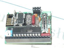
This time I would like to present the I2C clock synchronizer with time downloaded from the Internet. Using the previously presented clock on the Z8, I thought it would be worth extending it with this possibility, hence the presented circuit was created.
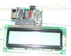
The system itself is based on the ESP8266-01 module, which obtains the time from the NTP server after logging into the WiFi network. The module cooperates with the ATtiny4313 microcontroller, whose task is generally to be seen as an I2C slave with address 0x0A by the clock cooperating with this system, which is an I2C master. In addition to serving as an I2C slave device, the microcontroller also operates the ESP8266 module via UART and supports an optional LCD display as a monitor of data exchanged via I2C with the master. You may ask why I didn't implement the I2C slave function in the ESP itself? Well, I didn't succeed. Multiple attempts (also using external interrupts to which ESP can respond) did not bring the expected effect. Here: https://github.com/esp8266/Arduino/issues/5762
there is even a discussion about it. So, in order to continue with this project, I decided to use an additional microcontroller. The microcontroller periodically sends data received from the I2C master to the WiFi module to log in to the WiFi network. Cyclic, because after turning on the power, the I2C master sends the SSID and password (both ending with CR and LF) needed to log in to the described synchronizer system once, and at that moment the WiFi network may not be available. After the ESP8266 module successfully establishes a connection to WiFi, the module periodically sends the received RSSI, time and date data to the microcontroller in the form of an 8-element int16 array. The ATtiny4313 microcontroller receives this data from the module, makes sure that the data is in the right order, and then transfers the ordered data to a buffer intended for reading by the I2C master. The optional display presents the SSID on the first line and the password received from the I2C master on the second line, and after establishing an Internet connection, displays the contents of the buffer for reading by the I2C master.
The representation of data placed in the correct order in the buffer and ready to be read by the I2C master is as follows:
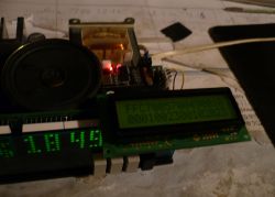
Where:
first element of this buffer: RSSI; a value less than 0 (0xFFC7 from LCD) means establishing an Internet connection; the lack of this connection is signaled by the value 0x001F
second element of this buffer: seconds in BCD (0057 from LCD)
third element of this buffer: minutes in BCD (0049 from LCD)
fourth element of this buffer: hours in BCD (0018 from LCD)
the fifth element of this buffer: day of the week; 1 - Monday, ..., 7 - Sunday (0001 from LCD)
sixth element of this buffer: day of the month in BCD (0023 from LCD)
seventh element of this buffer: month in BCD (0010 from LCD)
eighth element of this buffer: year in BCD (2023 from LCD).
The video on YT shows the synchronization of the clock, deliberately set to January 1, 2001, with the time downloaded from the Internet by the described module.
Now a little about the preparations for this project. When I was thinking about this project, I first came across the website: https://randomnerdtutorials.com/esp8266-nodemcu-date-time-ntp-client-server-arduino/
This is almost the finished product on which I based my sketch in the Arduino environment. Even this worked, but the inconvenience was the lack of automatic change of summer/winter time (despite the presence of the tm_isdst component in the tm structure, however, the value of this component did not change when switching from winter to summer time in spring). Moreover, the author asked us to add/subtract the number of hours expressed in seconds to the UTC time received by the module programmed with this example sketch, depending on the expected time zone. While looking for how to solve the above problems, I finally found the website: https://werner.rothschopf.net/202011_arduino_esp8266_ntp_en.htm
and after matching this sketch to our time zone using #define MY_TZ, the program began to correctly display the time in Poland on the terminal. After that, it remained only to adapt the sketch to the needs of cooperation with the described system.
A few more words about preparing the ESP8266 module itself to work with this system. Apart from adjusting the voltage levels on UART (module powered by 3.3V, ATTiny powered by 5V), which I implemented as described at http://mirekk36.blogspot.com/2015/05/konwerter-levelow-33v-ttl.html, the module itself must be programmed with the NTP_time_date.ino sketch. To do this you need:
1. Disconnect power from the module.
2. Short-circuit pins 2-1 with jumper JP1
3. Connect e.g. the ZL4USB adapter to the J2 socket. The pin arrangement in the J2 socket is adapted to the adapter I have.
4. Short pin 5 (GPIO0/Flash) of the ESP8266-01 module to ground using a microswitch.
5. With pin 5 shorted to ground, supply power to the module
6. You can now disconnect the connection from point 4. The module is now in firmware update mode.
7. In the Arduino 1.8.5 environment (this is what I use), compile and upload the NTP_time_date.ino sketch to the module
8. After uploading the sketch, disconnect and connect the power supply to the module again
9. Open e.g. RealTerm and connect to the module, connection parameters 19200.8N1.
10. Send the module the SSID name and password (both strings ending with CR LF, max. 14 characters in the string) for the WiFi network to which we want to connect. The characters of the sent SSID and password should be displayed in the appropriate lines on the connected LCD.
11. After successful connection, the module should periodically send data to RealTerm, as in the screenshot. This data will also be presented on the connected LCD.
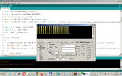
If you are unable to complete the above points 7...11 (the firmware in the module may be inappropriate), you should update the firmware (which works for it). For this purpose:
1. Download the firmware with flasher from https://www.elektroda.pl/rtvforum/topic3844441.html.
2. Follow steps 1...6 above to enter firmware update mode.
3. Run the ESP8266Flasher.exe file
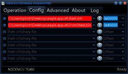
4. In this program, in the Config tab, indicate the files eagle.app.v6.flash.bin and eagle.app.v6.irom0text.bin as in the screenshot:
5. Then, in the Operation tab of this program, select the appropriate COM Port and press the Flash button.
6. After successfully uploading the firmware, try again to upload the NTP_time_date.ino sketch according to the above points 1...11
I wrote the program for ATtiny4313 in the Rowley Crossworks for AVR ver.1.4 IDE.
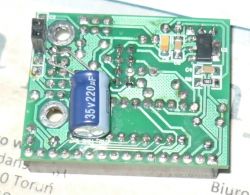
To sum up: the clock with this synchronizer works well, at least I have a reference time according to which I can set other clocks in the house. I also had to equip the described system with:a 220uF capacitor connected to the 5V side (visible in one of the photos), because during startup it turned out that when the WiFi network was lost (e.g. when the router was turned off), the Z8681 clock microcontroller could hang. The reason was a drop in the 5V voltage supplying the clock. An example of the cooperation of the described system with the Z8681 clock is here:
https://www.elektroda.pl/rtvforum/topic3795375.html
Regards, KT
Cool? Ranking DIY


