logo elektroda
logo elektroda
X
logo elektroda

How to connect the 3.3V circuit to GPIO2 on the ESP01 for state detection?

Vexator 678 11
ADVERTISEMENT
Treść została przetłumaczona polish » english Zobacz oryginalną wersję tematu
  • #1 20889485
    Vexator
    Level 10  
    Hey,
    in ESP01 I have a status check on GPIO2. When I connect GND, it shows 1, when I disconnect it shows 0.
    I have a circuit for this (shared VCC and GND with the one from ESP) with a physical switch and LED.
    I would like to check if this additional circuit is closed, but there is 3.3v on it, not GND.

    How to connect one to the other? Some transistor between GND and GPIO2, with the middle leg to my circuit? Just which one? I'm completely green in these matters :/.
  • ADVERTISEMENT
  • #2 20889506
    jarekgol
    Level 39  
    Vexator wrote:
    When I connect GND, it appears 1, when I disconnect, it appears 0.

    Is it somehow the other way around? And "appears" means where does it appear, where and how do you see it?

    Normally when you want to connect a pin to a controller, you connect GPIO.n to the pin, the pin to ground and enable pull-up on the port, or you give an external resistor to + and GPIO.n
    You can also pin from + to the port if the controller supports pull-down or add a resistor to ground.
  • ADVERTISEMENT
  • #3 20889550
    Vexator
    Level 10  
    jarekgol wrote:
    Vexator wrote:
    When I connect GND, a 1 appears, when I disconnect, a 0 appears.

    Is it somehow the other way around? And "appears" means where does it appear, where and how do you see it?
    in software
    jarekgol wrote:
    Normally when you want to connect a pin to a controller, you connect GPIO.n to the pin, pin to GND and you turn on the pull-up on the port
    and that would work beautifully with GND, and I need it with VCC
    jarekgol wrote:
    , or you give an external resistor to + and GPIO.n
    You can also pin from + to port if the controller supports pull-down or add a resistor to ground.

    pull-down will not work. How else can I figure it out
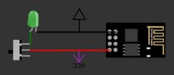
    I have roughly something like this:
    Diagram with a button, LED, and electronic module with VCC and GND labels. .
  • ADVERTISEMENT
  • #6 20890717
    Vexator
    Level 10  
    khoam wrote:
    GPIO2 on the ESP8266 has an internal pull-up and without connecting anything you should read 1.
    you're right, that was a mental shortcut on my part. The default is 1, when GND is connected it's 0, but I reversed that in the code
    jarekgol wrote:
    or light the led from the switch and know its status?
    Describe somehow in full sentences what the work is in.
    This switch in the picture is the only one I found in the simulator, in reality there is a simple ON/OFF.
    In full sentences the work:
    I have a 3.3V DC power supply in the fuse box. To it is connected (under -) the wire that goes into the wall. Later it comes back and is connected under the diode and further to the power supply (under +).
    I can power it the other way round and it also works (after reversing the diode).
    This wire goes to the liquid tank and when there is a lot of liquid, it starts to pass current, the diode starts to light up.
    From the same power supply, I powered ESP01 in parallel.
    I want to check if the diode lights up (or more precisely, if the current is flowing and not through the photodiode ;) )
  • #7 20891471
    jarekgol
    Level 39  
    It would probably be nicer to give a comparator on the way there, but as it lights up for you, it should work.
    Be careful, because such a level check, can eat the cables due to electrolysis.

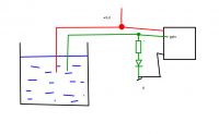
    ps. You may still have to give some resistor to ground from that green test line, but that will come out in the wash.
  • #8 20891666
    khoam
    Level 42  
    GPIO2 must not be connected to ground. This will cause problems with booting the ESP01.
  • ADVERTISEMENT
  • #9 20892200
    Vexator
    Level 10  
    jarekgol wrote:
    Be careful, because checking the level like this, can eat the cables because of the electrolysis.
    I don't know what's in the tank, but the led has been running for a dozen years, so maybe there's a float in there that turns the circuit on dry?
    Maybe I misunderstand your drawing, but when the liquid level increases, doesn't a `+` appear on the GPIO when I need a `-`?
    My knowledge of electronics is low, so forgive me if I write some stupid stuff.... can't I do this by connecting an NPN transistor with the outer legs to GND and GPIO, and the middle leg between the LED and the tank?
    khoam wrote:
    GPIO2 must not be connected to GND. This will cause problems booting the ESP01.
    does this apply to both GPIO0 and GPIO2?
  • Helpful post
    #10 20892375
    khoam
    Level 42  
    Vexator wrote:
    does this apply to both GPIO0 and GPIO2?

    Yes, this information is included in the link I provided earlier.
    Text regarding boot failure conditions for GPIO0 and GPIO2. Text regarding boot failure conditions for GPIO0 and GPIO2. .
  • #11 20892949
    jarekgol
    Level 39  
    As for the 0.1 you can
    1) embrace it programmatically
    2) Reverse engineer my schematic (as you draw, you can throw in to check.
    3) Negate it hardware-wise, i.e. transistor, while remembering to have a resistor at least a few kilo ohms in the base.

    Maybe look into the tank and see what's there ;)


    @khoam what is this functionality used for? Because in this article it says that "can be prevented from booting if some pins are pulled LOW or HIGH. " but for what, I don't see.

    Any direct access to memory in such a state?
  • #12 20893003
    khoam
    Level 42  
    jarekgol wrote:
    what is this functionality used for? Because in this article it says that "can be prevented from booting if some pins are pulled LOW or HIGH. " but for what, I don't see.
    To choose boot mode: normal, programming (over UART) or booting from an external SD card. In the first two modes GPIO2 must be in high state.

Topic summary

The discussion revolves around connecting a 3.3V circuit to GPIO2 on the ESP01 for state detection. The user describes a setup where connecting GND to GPIO2 results in a low state (0), while disconnecting it results in a high state (1). The user seeks advice on how to connect a circuit that operates at 3.3V to GPIO2, considering the internal pull-up resistor of the ESP8266. Suggestions include using an NPN transistor to interface the circuit with GPIO2, ensuring that the GPIO pin does not connect directly to GND to avoid boot issues. The importance of using resistors and the potential for electrolysis in the circuit are also discussed. The user is advised to check the circuit design and consider the implications of the liquid level on the GPIO state.
Summary generated by the language model.
ADVERTISEMENT