Hi,
The moment is approaching to equip my new house with electrics, lighting and an alarm system and I have started to prepare for a Smart Home. Ready-made solutions don't satisfy me, and on top of that they are horrendously expensive, so I'm developing something of my own.
At first I thought about using ready-made modules from aliexpress and making a spider web on the backplane, I see a lot of people doing this and it's quite effective, but I've seen a few people replacing it with something more integrated made to their own design.
My objectives are as follows:
- professional appearance - DIN TH35 enclosures,
- full modularity - one control board for many applications, based on ESP32,
- additional boards for specific functions,
- communication over CAN - proven multi-master protocol supported by many devices and systems,
- free power supply of circuits (not connected to control circuits),
- possibility to use any software such as ESP Home, ESP Easy or any SDK such as Arduino, etc.
Physical design:
- use of some inexpensive and universal DIN housing
- base size is two modules
- placement of the boards as follows:
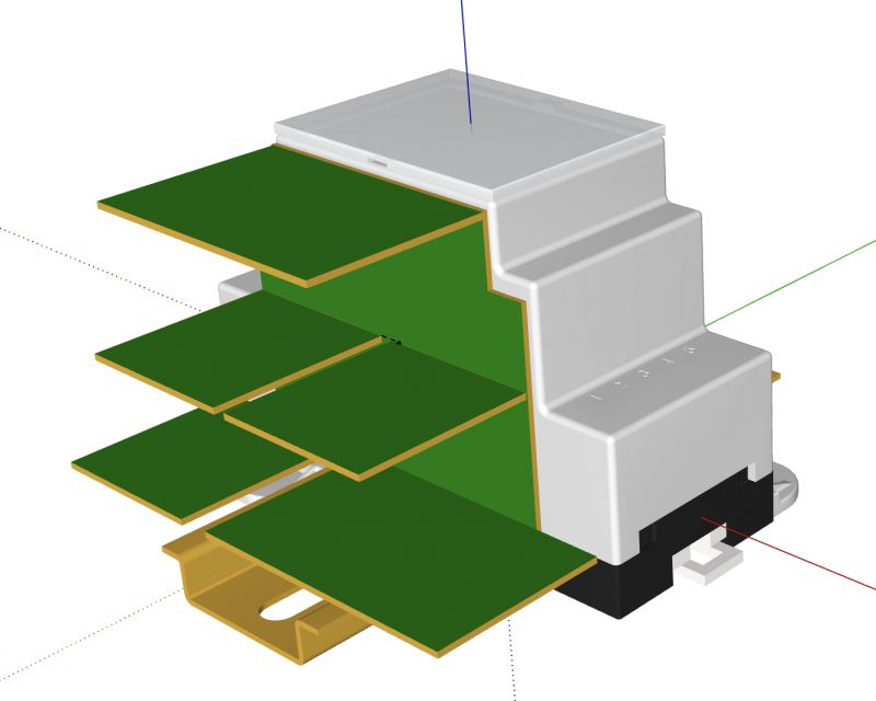
- possibility to combine function boards in length
- possibility to place two and more sets of boards in one enclosure in order to increase the number of IO
- connection of modules by means of sockets in the side walls of the enclosure and goldpins, the only disadvantage is that the module will have to be moved before removal, if this is a misfire I will work out some other way of connecting, if I found some nice connectors with spring pins at 1mm it would be ideal
The available number of IO will depend on the ESP32 model:
- ESP32-WROOM-32 - 20 GPIOs will realistically be available (including 4 input-only),
- ESP32-S3-WROOM-2 - 27 GPIOs to be used,
- ESP32-S2-SOLO-2 - 31 GPIOs to be used.
Why 3 different ESP32 modules? The classic ESP32 is recognised as proven in virtually every project, the WLED allows hardware control of 10 WS281x channels. ESP32-S2/S3 have more GPIOs but most projects have not found them completely proven.
Why not port expanders e.g. MCP23017? One ESP32 costs as much as two expanders, but has incomparable capabilities and more ports.
In addition to the specified quantities, each control board will have the following outputs:
- CAN TX/RX,
- serial TX/RX,
- 1WIRE for temperature sensors,
- RESET button, to which line as output will be connected WS2812b LED showing the status,
- BOOT button, to be used arbitrarily when not programming the circuit,
- power supply status LEDs 3.3V and 5V (1mA) status LEDs,
- if OLED I2C display will be used then the number of GPIOs will be reduced by 2.
Planned board types (width 2 DIN modules), possibility to place up to 4 boards in one housing:
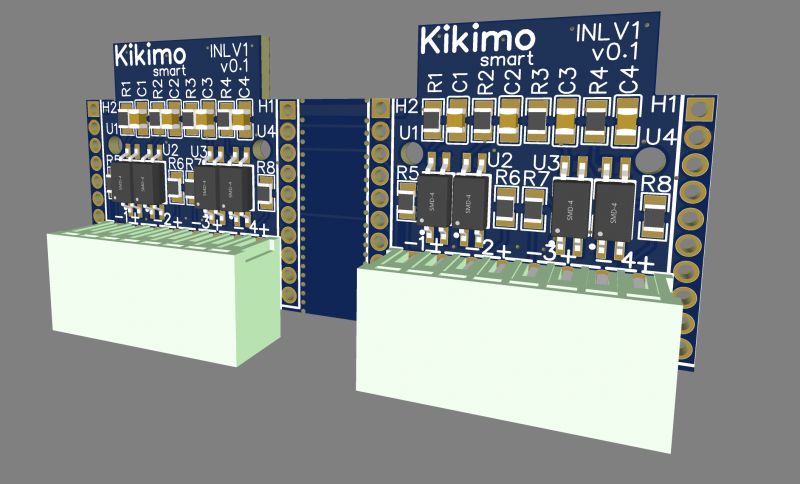
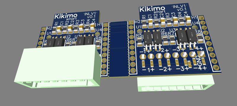
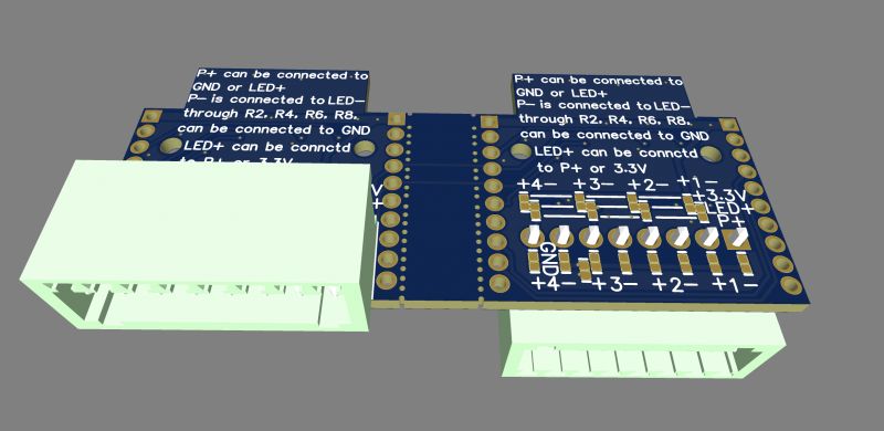
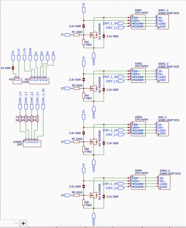
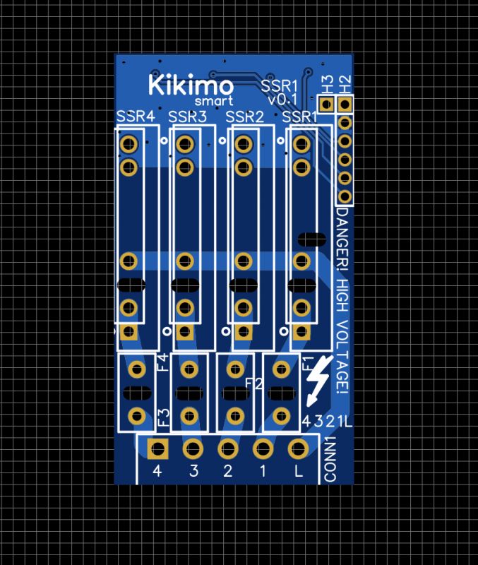
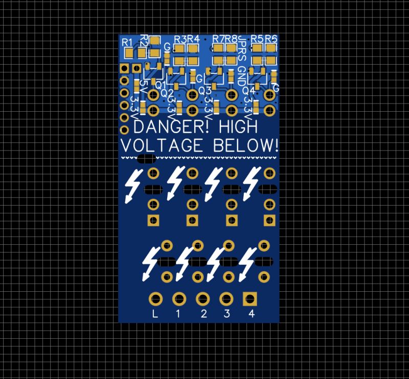
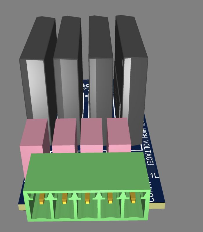
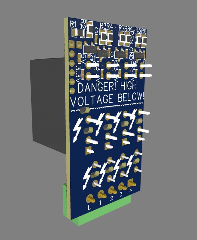
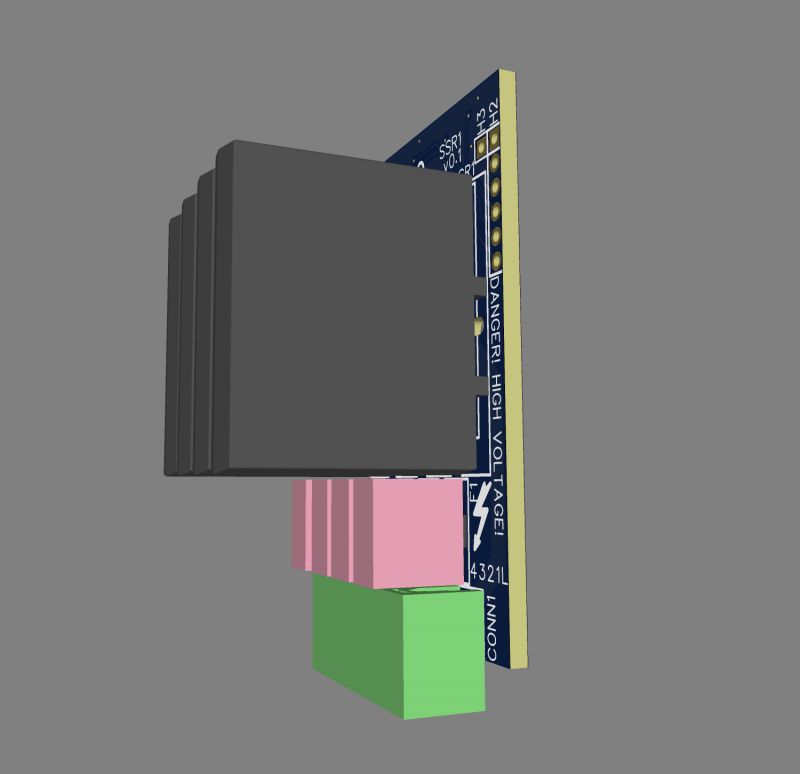
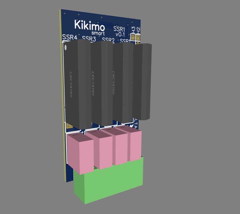
- 4x SSR 2A board,
- 4x relay 5A board (common input),
- 2x relay 10/16A board (NO/NC), to be used e.g. at roller shutters,
- pixel/PWM/MOSFET board: 4x MOSFET + 4 isolated outputs to control WS281x,
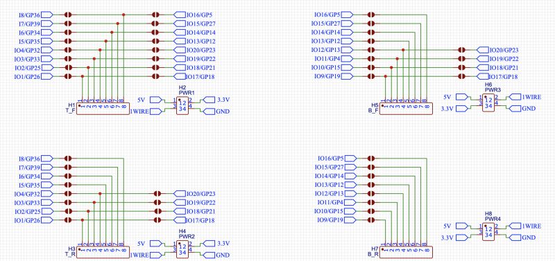
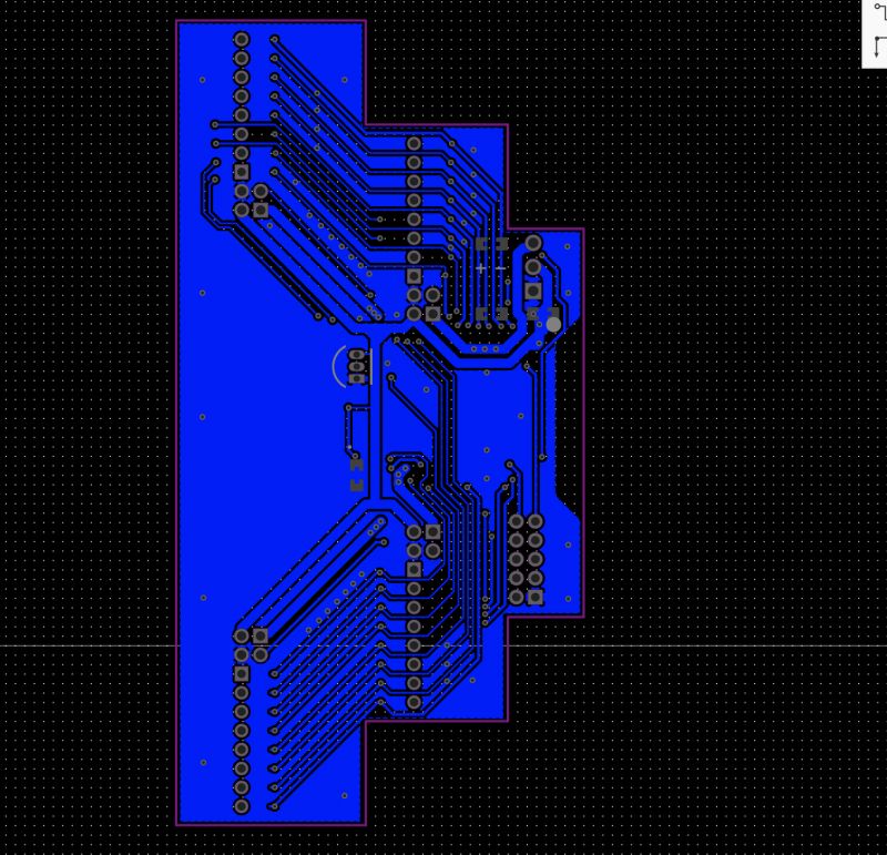
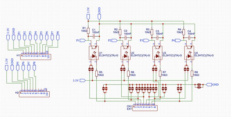
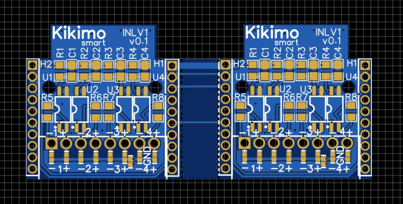
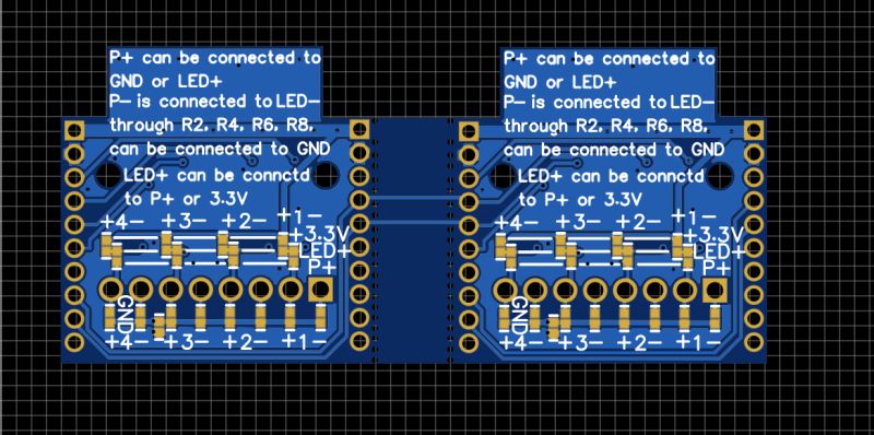
- IO board: 2 RJ45 connectors on board, optically isolated, can be mounted in pairs. on the top and bottom of the board, i.e. a total of 8 RJ45s with the possibility of relatively free configuration of all 20-31 GPIOs via a matrix of solderable jumpers on the PCB.
-an alternative IO board with plug connectors (screwed alb springs), 12 pins per board,
- CAN-CAN-ETH board, connecting the internal CAN of the system to the ethernet and separated CAN e.g. for the needs of can2mqtt.
The boards will be able to be mounted in any configuration, i.e. executive boards at the bottom, input boards at the top (or vice versa if you wish).
The boards will have twisted or spring-loaded plug connectors, adapted to the current load.
I plan to use the IO boards also for DIY alarm, instead of optocouplers by mounting waktrols to obtain parametric lines.
I have done a review of the two series of DIN enclosures here:
https://www.elektroda.pl/rtvforum/topic4029847.html
Added after 1 [hour] 7 [minutes]:
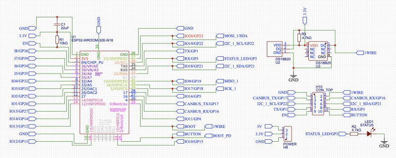
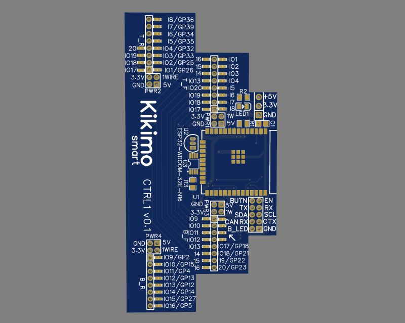
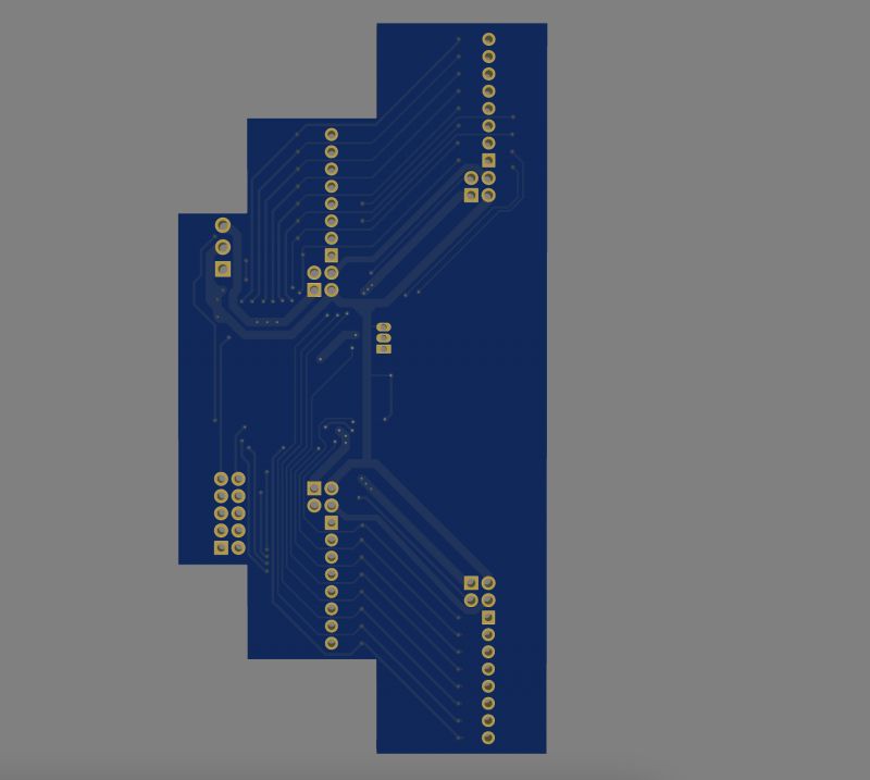
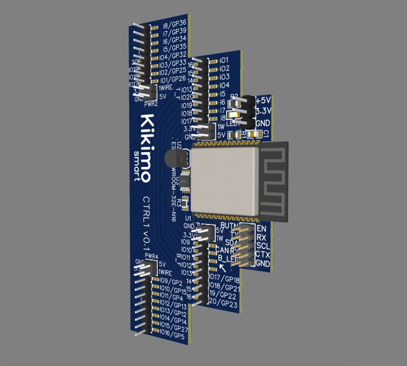
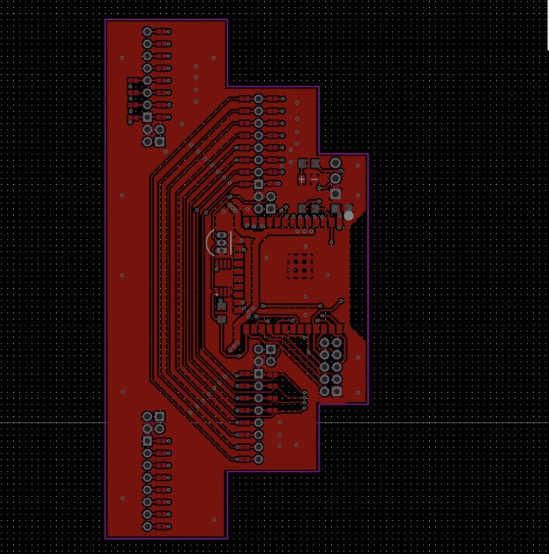
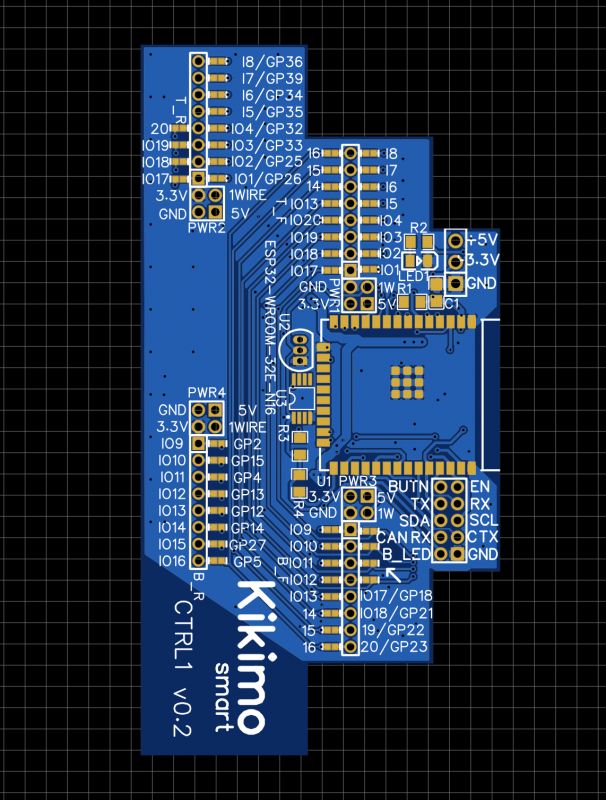
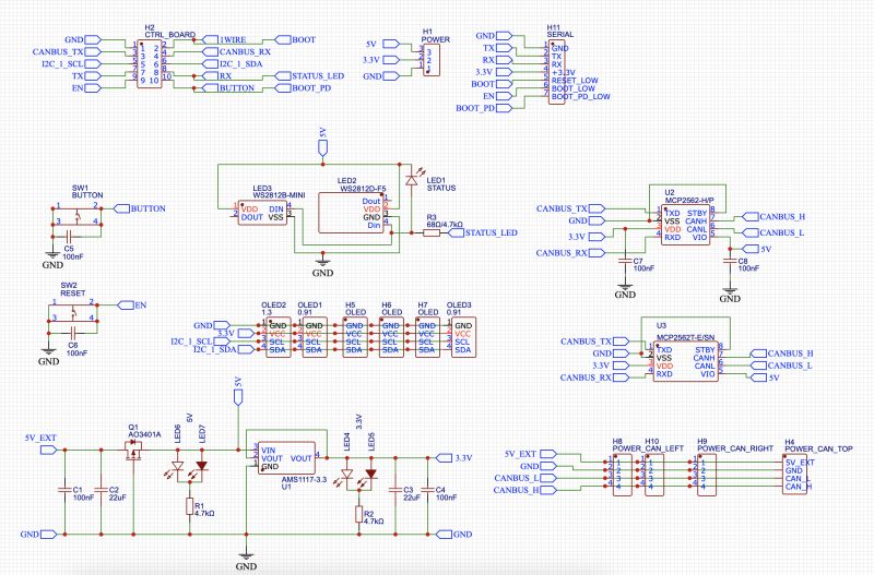
Control board
ESP32-.WROOM-32E
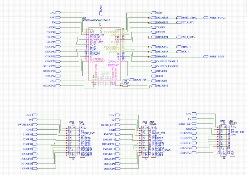
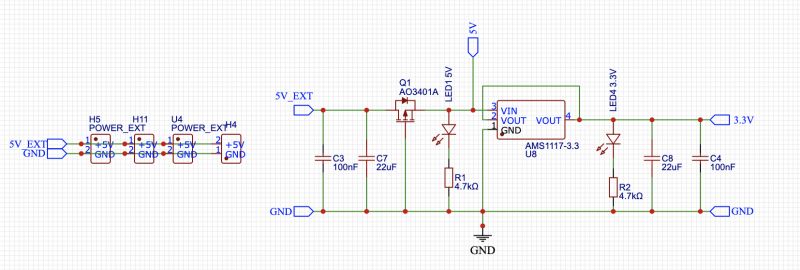
Power section, protected against reverse polarity by a MOSFET
CAN and serial

Programmable status LED (WS2812b or regular LED depending on preference), connected to GPIO0, which is generally difficult to use, but for this.

Optional OLED display (for those interested - single colour draws about 20mA), and in my opinion the very important 1Wire for temperature measurement, especially of relays/SSRs/MOSFETs.

Added after 2 [minutes]:
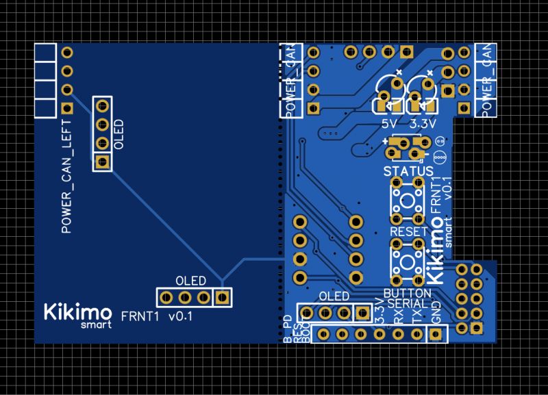
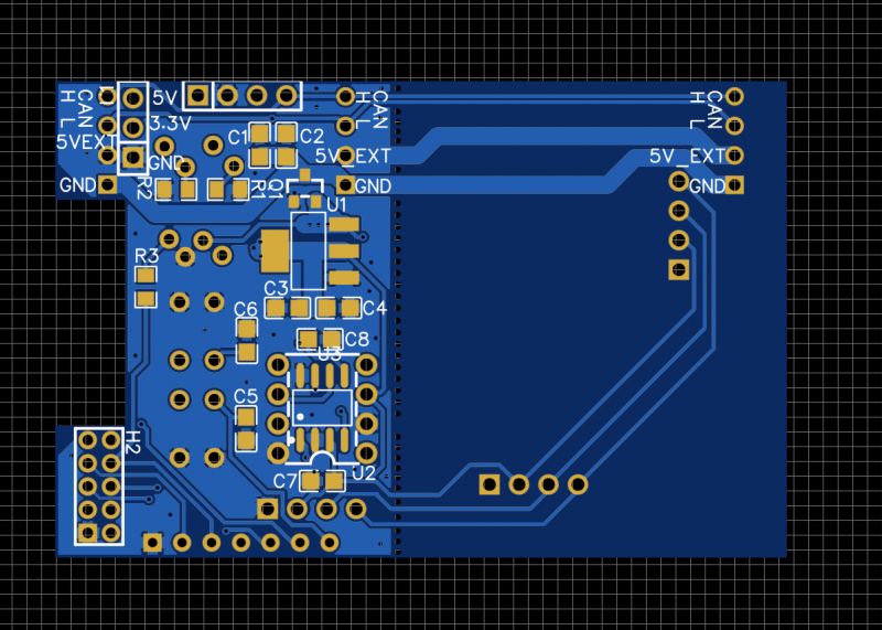
I've also designed the board, but in the meantime I've changed the concept, originally I was thinking of a control board on the front of the chassis and connecting by tapes with connectors JST1.25, now I have to design it on the side with solder joints.
The moment is approaching to equip my new house with electrics, lighting and an alarm system and I have started to prepare for a Smart Home. Ready-made solutions don't satisfy me, and on top of that they are horrendously expensive, so I'm developing something of my own.
At first I thought about using ready-made modules from aliexpress and making a spider web on the backplane, I see a lot of people doing this and it's quite effective, but I've seen a few people replacing it with something more integrated made to their own design.
My objectives are as follows:
- professional appearance - DIN TH35 enclosures,
- full modularity - one control board for many applications, based on ESP32,
- additional boards for specific functions,
- communication over CAN - proven multi-master protocol supported by many devices and systems,
- free power supply of circuits (not connected to control circuits),
- possibility to use any software such as ESP Home, ESP Easy or any SDK such as Arduino, etc.
Physical design:
- use of some inexpensive and universal DIN housing
- base size is two modules
- placement of the boards as follows:

- possibility to combine function boards in length
- possibility to place two and more sets of boards in one enclosure in order to increase the number of IO
- connection of modules by means of sockets in the side walls of the enclosure and goldpins, the only disadvantage is that the module will have to be moved before removal, if this is a misfire I will work out some other way of connecting, if I found some nice connectors with spring pins at 1mm it would be ideal
The available number of IO will depend on the ESP32 model:
- ESP32-WROOM-32 - 20 GPIOs will realistically be available (including 4 input-only),
- ESP32-S3-WROOM-2 - 27 GPIOs to be used,
- ESP32-S2-SOLO-2 - 31 GPIOs to be used.
Why 3 different ESP32 modules? The classic ESP32 is recognised as proven in virtually every project, the WLED allows hardware control of 10 WS281x channels. ESP32-S2/S3 have more GPIOs but most projects have not found them completely proven.
Why not port expanders e.g. MCP23017? One ESP32 costs as much as two expanders, but has incomparable capabilities and more ports.
In addition to the specified quantities, each control board will have the following outputs:
- CAN TX/RX,
- serial TX/RX,
- 1WIRE for temperature sensors,
- RESET button, to which line as output will be connected WS2812b LED showing the status,
- BOOT button, to be used arbitrarily when not programming the circuit,
- power supply status LEDs 3.3V and 5V (1mA) status LEDs,
- if OLED I2C display will be used then the number of GPIOs will be reduced by 2.
Planned board types (width 2 DIN modules), possibility to place up to 4 boards in one housing:
- 4x SSR 2A board,
- 4x relay 5A board (common input),
- 2x relay 10/16A board (NO/NC), to be used e.g. at roller shutters,
- pixel/PWM/MOSFET board: 4x MOSFET + 4 isolated outputs to control WS281x,
- IO board: 2 RJ45 connectors on board, optically isolated, can be mounted in pairs. on the top and bottom of the board, i.e. a total of 8 RJ45s with the possibility of relatively free configuration of all 20-31 GPIOs via a matrix of solderable jumpers on the PCB.
-an alternative IO board with plug connectors (screwed alb springs), 12 pins per board,
- CAN-CAN-ETH board, connecting the internal CAN of the system to the ethernet and separated CAN e.g. for the needs of can2mqtt.
The boards will be able to be mounted in any configuration, i.e. executive boards at the bottom, input boards at the top (or vice versa if you wish).
The boards will have twisted or spring-loaded plug connectors, adapted to the current load.
I plan to use the IO boards also for DIY alarm, instead of optocouplers by mounting waktrols to obtain parametric lines.
I have done a review of the two series of DIN enclosures here:
https://www.elektroda.pl/rtvforum/topic4029847.html
Added after 1 [hour] 7 [minutes]:
Control board
ESP32-.WROOM-32E

Power section, protected against reverse polarity by a MOSFET

CAN and serial

Programmable status LED (WS2812b or regular LED depending on preference), connected to GPIO0, which is generally difficult to use, but for this.

Optional OLED display (for those interested - single colour draws about 20mA), and in my opinion the very important 1Wire for temperature measurement, especially of relays/SSRs/MOSFETs.

Added after 2 [minutes]:
I've also designed the board, but in the meantime I've changed the concept, originally I was thinking of a control board on the front of the chassis and connecting by tapes with connectors JST1.25, now I have to design it on the side with solder joints.


