Hello.
I'm new and this is my first disassembly. I hope you like it.
(Sorry for the translation. I use Google)
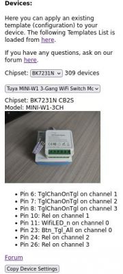
It is a 3-channel switch with BK7231N.
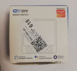

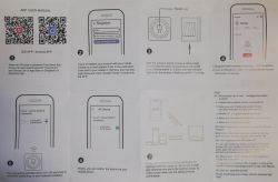
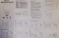
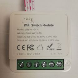
Here the disassembly had already begun. I don't have previous photos.
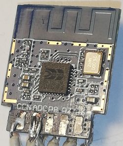
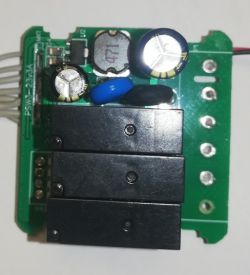
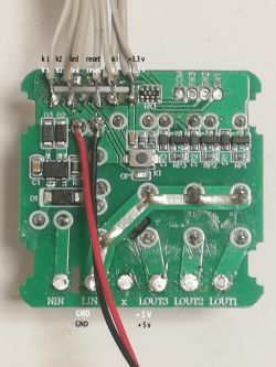
For tests. Soldered wiring (lousy soldering).
The Tx and Rx connections are used for the LED integrated on the board and for the K1.
Power with 5 V in the capacitor before the 3.3 V LDO.
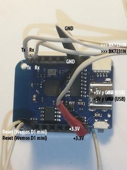
As a programmer, I tried Wemos D1 mini (clone), with excellent results. We connect the reset (of the Wemos D1 mini) to GND to sleep the ESP8266.
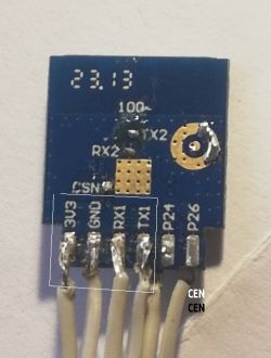
When flashing with BK7231Flaser.exe (with Mono on Linux) I got an error. The memory was erased fine but when writing it gave an error.
Then I thought it would be a permissions problem but I was already trying with python.
A touch from CEN to GND and recording…

Perfect.
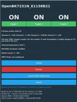
A reset and the connection was immediate:
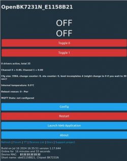
It is not configured (I have to study it as I am still a newbie). That's why only two buttons appear instead of three. The action on them seems good.
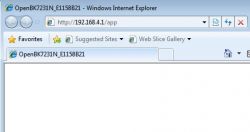
But when launching the web application, it failed.

I thought it could be through the browser or mobile phone and I connected from the laptop, without success.
And I noticed that it only allows me one connection. Or mobile, or laptop.
I don't know if I'm doing something wrong.
Added after 11 [hours] 26 [minutes]:
I continue trying to upload with BK7231Flasher but it throws the error:

Added after 22 [minutes]:
Well. From Windows I have had no problem flashing,

but I still have an error when launching the web application.
I'm new and this is my first disassembly. I hope you like it.
(Sorry for the translation. I use Google)
It is a 3-channel switch with BK7231N.


Here the disassembly had already begun. I don't have previous photos.


For tests. Soldered wiring (lousy soldering).
The Tx and Rx connections are used for the LED integrated on the board and for the K1.
Power with 5 V in the capacitor before the 3.3 V LDO.

As a programmer, I tried Wemos D1 mini (clone), with excellent results. We connect the reset (of the Wemos D1 mini) to GND to sleep the ESP8266.


When flashing with BK7231Flaser.exe (with Mono on Linux) I got an error. The memory was erased fine but when writing it gave an error.
Then I thought it would be a permissions problem but I was already trying with python.
A touch from CEN to GND and recording…
Perfect.
A reset and the connection was immediate:

It is not configured (I have to study it as I am still a newbie). That's why only two buttons appear instead of three. The action on them seems good.
But when launching the web application, it failed.

I thought it could be through the browser or mobile phone and I connected from the laptop, without success.
And I noticed that it only allows me one connection. Or mobile, or laptop.
I don't know if I'm doing something wrong.
Added after 11 [hours] 26 [minutes]:
I continue trying to upload with BK7231Flasher but it throws the error:
Added after 22 [minutes]:
Well. From Windows I have had no problem flashing,
but I still have an error when launching the web application.


