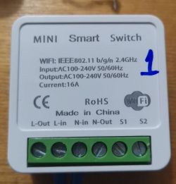
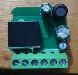
I came across a seemingly ordinary smart switch.
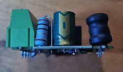
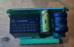
But inside there is some kind of simplified version with a BK7231N chip.
At first I decided to flash it with Tuya-Convert, but the version of the native firmware was 1.3.10 and it did not allow flashing wirelessly.
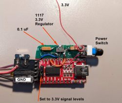
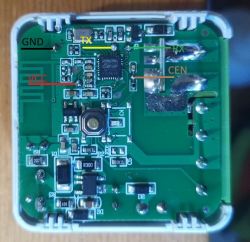
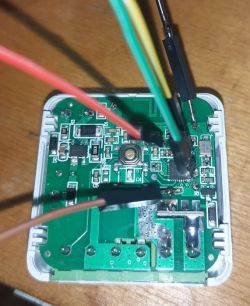
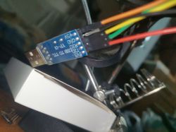
After calling the contacts, I decided to flash it in the usual way.
I did not need the CEN contact for the firmware.
Everything went well.

But inside there is some kind of simplified version with a BK7231N chip.


At first I decided to flash it with Tuya-Convert, but the version of the native firmware was 1.3.10 and it did not allow flashing wirelessly.
After calling the contacts, I decided to flash it in the usual way.
I did not need the CEN contact for the firmware.
Everything went well.


{
	"rl1_lv":"1",
	"on_off_cnt":"10",
	"onoff_rst_m":"1",
	"onoff_clear_t":"10",
	"rand_dpid":"42",
	"net_trig":"2",
	"onoff_n":"3",
	"netled1_lv":"1",
	"jv":"102",
	"onoff_rst_type":"2",
	"total_bt_pin":"23",
	"nety_led":"2",
	"total_stat":"2",
	"reset_t":"5",
	"netled1_pin":"26",
	"remote_add_dp":"49",
	"remote_list_dp":"50",
	"net_type":"0",
	"inch_dp":"44",
	"module":"CB2S",
	"ch_cddpid1":"9",
	"onoff1":"6",
	"clean_t":"5",
	"init_conf":"38",
	"zero_select":"0",
	"onoff_type":"0",
	"series_ctrl":"0",
	"total_bt_lv":"0",
	"cyc_dpid":"43",
	"remote_select":"0",
	"ch_num":"1",
	"rl1_pin":"7",
	"netn_led":"2",
	"ch_dpid1":"1",
	"crc":"6",
	"}PPAgw_di{abi":"0",
	"id":"null",
	"swv":"1.3.10",
	"bv":"40.00",
	"pv":"2.2",
	"lpv":"3.4",
	"pk":"keyjnuy4s3kre7m7",
	"firmk":"keyjnuy4s3kre7m7",
	"cadv":"1.0.5",
	"cdv":"1.0.0",
	"dev_swv":"1.3.10",
	"s_id":"null",
	"dtp":"0",
	"sync":"0",
	"attr_num":"1",
	"mst_tp_0":"9",
	"mst_ver_0":"1.3.10",
	"mst_md5_0":"null",
	"mst_tp_1":"0",
	"mst_ver_1":"null",
	"mst_md5_1":"null",
	"mst_tp_2":"0",
	"mst_ver_2":"null",
	"mst_md5_2":"null",
	"mst_tp_3":"0",
	"mst_ver_3":"null",
	"mst_md5_3":"null }xAinch_time_key{ch0",
	"ssid":"dnRydXN0LWZsYXNo",
	"passwd":"null",
	"md":"1",
	"random":"0",
	"wfb64":"1",
	"stat":"0",
	"token":"00000000",
	"region":"US",
	"reg_key":"0101",
	"dns_prio":"0 "
}Device configuration, as extracted from Tuya:
- Pair/Toggle All Button on P23
- WiFi LED on P26
- TglChannelToggle (channel 1) on P6
- Relay (channel 1) on P7
Device seems to be using CB2S module, which is using BK7231N.
And the Tuya section starts, as usual, at 2023424Cool? Ranking DIY


