logo elektroda
logo elektroda
X
logo elektroda

[BK7231N] AUBESS Power Monitor Switch - Setting Up Power Measurement Channel

brazoayeye 1185 15
ADVERTISEMENT
  • #1 21209568
    brazoayeye
    Level 4  
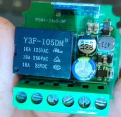
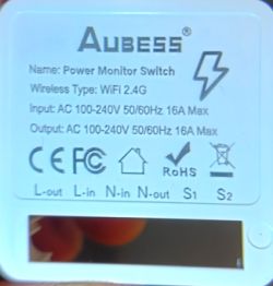
    I bought this AUBESS "Power Monitor Switch"

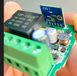
    I umounted it, founding a BK7231N
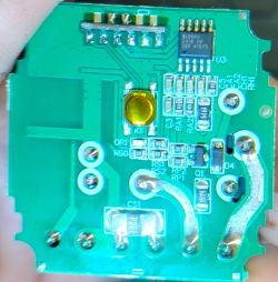
    Connected 3.3V, GND, TX, RX under the small board

    Backed up using BK7231Flasher , and then flashed latest openBK

    Following the found json
    Spoiler:
    {
    "rl1_lv":"1",
    "on_off_cnt":"5",
    "onoff_rst_m":"1",
    "onoff_clear_t":"5",
    "rand_dpid":"42",
    "net_trig":"4",
    "onoff_n":"5",
    "netled1_lv":"0",
    "jv":"102",
    "onoff_rst_type":"2",
    "total_bt_pin":"23",
    "nety_led":"2",
    "over_cur":"0",
    "total_stat":"0",
    "reset_t":"5",
    "netled1_pin":"8",
    "chip_type":"3",
    "lose_vol":"0",
    "remote_add_dp":"49",
    "remote_list_dp":"50",
    "net_type":"0",
    "over_vol":"0",
    "inch_dp":"44",
    "module":"CB2S",
    "ch_cddpid1":"9",
    "onoff1":"24",
    "clean_t":"5",
    "init_conf":"38",
    "zero_select":"0",
    "onoff_type":"0",
    "series_ctrl":"2",
    "total_bt_lv":"0",
    "cyc_dpid":"43",
    "remote_select":"0",
    "ch_num":"1",
    "rl1_pin":"26",
    "ele_rx":"10",
    "netn_led":"2",
    "vol_def":"0",
    "ch_dpid1":"1",
    "ele_tx":"11",
    "crc":"48"
    }
    Device configuration, as extracted from Tuya:
    - Pair/Toggle All Button on P23  => it's the board button, P23 = ADC3 https://docs.libretiny.eu/boards/cb2s/#pinout
    - WiFi LED on P8     => that's right
    - TglChannelToggle (channel 1) on P24  => it's the S1/S2 switch
    - Relay (channel 1) on P26  => right
    Device seems to be using CB2S module, which is using BK7231N.
    And the Tuya section starts, as usual, at 2023424

    How can i find and setup the channel for the power measurement?
    Attached some photos, do you need other infos?

    Thanks
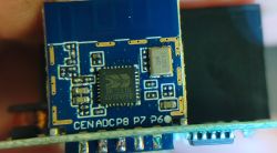
    Electronic module with BK7231N chip. Close-up of an AUBESS electronic switch board with visible components. Close-up of a printed circuit board with electronic components Back label of AUBESS power switch with technical specifications. Close-up of a circuit board with electronic components, including a CB2S module.
  • ADVERTISEMENT
  • #2 21209629
    p.kaczmarek2
    Moderator Smart Home
    BL0942 is always using UART1 for communication. You need to enter:
    
    startDriver BL0942
    in your either autoexec.bat or short startup command. Then reboot. Then you need to calibrate, like you'd do in Tasmota. VoltageSet/CurrentSet/PowerSet commands.

    For this kind of device, you also might need to enable PowerSave 1 so the device capacitors can last longer.
    Helpful post? Buy me a coffee.
  • ADVERTISEMENT
  • #3 21210158
    brazoayeye
    Level 4  
    Thanks for the info, so it's used a BL0942 and it communicates with the same TX/RX used for flashing.

    Can you provide a guide or a link where I can deepen how to calibrate it?

    At the end I want to flash espHome as I did in other devices without power metering, do you know if it's possible to read the current using it?

    When you write "this kind of devices" do you mean I should check also my other espHome DIY switch to enable some kind of low power mode? Example >>21126030

    Thanks
  • #4 21583952
    brazoayeye
    Level 4  
    I flashed another identical device, and I have many questions:

    1. S1-S2 switch gives me problems. P24 is TglChnOnTgl but when left unconnected it randomly double toggles (like 1 time every 3 seconds). Switch usually off but relay turns on and off very fast because of that false signal. If I short circuit S1 S2 the relay remains stable, but if I open S1 S2 it starts ticking again. I found a stable 3.3V between S1 and S2
    2. I wrote on startup_command "powersave 1; startDriver BL0942" but idk where I can read the power consumption. I tried to calibrate the device having this message
    Last command: VoltageSet 226
    Last status: ERROR: Unknown command (undefined) 


    If I go to the console and I write "startDriver BL0942" then I start having "Last status: OK (200)!"
    PS: when I enable the driver I also can read the measure, so why it doesn't start on boot?

    Thanks
  • #5 21583963
    p.kaczmarek2
    Moderator Smart Home
    Let's do one issue at time. Where do you enter startDriver command? Startup command is run after reboot. VoltageSet command is available once driver is started. There is information about running drivers in the main page.

    I don't know much about Esphome. Last time I checked it had just powersave copied from OBK by one of our user. OBK, on the other hand, is calibrated to utilize OBK powersave - as far as I remember it was done few years ago by @ btsimonh, who adjusted timers to allow longer dynamic sleep. Just keep in mind that device won't sleep if you keep web app log open.

    By "this kind of devices" I mean like smart plugs or smart switches. Or... or just enable PowerSave 1 on any OBK device. It should be okay since we adjusted PowerSave to take BL0937 into the account.
    Helpful post? Buy me a coffee.
  • #6 21584375
    brazoayeye
    Level 4  
    p.kaczmarek2 wrote:
    Let's do one issue at time. Where do you enter startDriver command? Startup command is run after reboot. VoltageSet command is available once driver is started. There is information about running drivers in the main page.

    From here:
    [BK7231N] AUBESS Power Monitor Switch - Setting Up Power Measurement Channel

    p.kaczmarek2 wrote:
    I don't know much about Esphome. Last time I checked it had just powersave copied from OBK by one of our user. OBK, on the other hand, is calibrated to utilize OBK powersave - as far as I remember it was done few years ago by @ btsimonh, who adjusted timers to allow longer dynamic sleep. Just keep in mind that device won't sleep if you keep web app log open.

    For now I stopped testing modules with EspHome because I saw they haven't got the same experience with this kind of cpus and I want to minimize surprises.
    For example I don't have time to test real module consumption with different firmware to check that consumption are comparable.
  • #7 21584469
    p.kaczmarek2
    Moderator Smart Home
    If you want to run multiple commands in line, you need to use backlog - like in Tasmota.
    [BK7231N] AUBESS Power Monitor Switch - Setting Up Power Measurement Channel
    So now, you need to either:
    - add backlog at the start of line
    OR
    - put each command in separate line

    In current state, second command is not run.
    Helpful post? Buy me a coffee.
  • #8 21584534
    brazoayeye
    Level 4  
    Thanks! I had missed that backlog was a keyword. I suggest to write something like: write one command in each line or use the keyword backlog to group them (ex "backlog cmd1; cmd2; cmd3)

    Do you have ideas regarding the S1 S2 problem?
    S1 is connected with N-OUT
    N-OUT have a 0.001 ohm to N-IN
    cpu GND is connected to N-out or N-in (idk which)
    S2 goes to RS0 (1k) and then directly to P24 (arrows)
    Screenshot of a system log console showing device operation logs and user commands related to channel control, MQTT, and state changes.

    Screenshot of MQTT system logs and user questions about electronics debugging and command handling in software.

    Do you know if there is a capacitor between S1 and S2 that I should check?

    Thanks

    Added after 20 [minutes]:

    
    Info:MAIN:Time 61, idle 70067/s, free 61992, MQTT 0(0), bWifi 0, secondsWithNoPing -1, socks 6/38 POWERSAVE
    Info:MQTT:Channel has changed! Publishing 1 to channel 2 
    Info:MQTT:Channel has changed! Publishing 0 to channel 2 
    Info:MAIN:Time 62, idle 69054/s, free 70600, MQTT 0(0), bWifi 0, secondsWithNoPing -1, socks 5/38 POWERSAVE
    Info:MAIN:Time 63, idle 78461/s, free 70600, MQTT 0(0), bWifi 0, secondsWithNoPing -1, socks 5/38 POWERSAVE
    Info:MAIN:Time 64, idle 73866/s, free 70600, MQTT 0(0), bWifi 0, secondsWithNoPing -1, socks 5/38 POWERSAVE
    Info:MAIN:Time 65, idle 75561/s, free 70600, MQTT 0(0), bWifi 0, secondsWithNoPing -1, socks 5/38 POWERSAVE
    Info:MAIN:Time 66, idle 76257/s, free 70600, MQTT 0(0), bWifi 0, secondsWithNoPing -1, socks 5/38 POWERSAVE
    Info:MAIN:Time 67, idle 75214/s, free 70600, MQTT 0(0), bWifi 0, secondsWithNoPing -1, socks 5/38 POWERSAVE
    Info:MQTT:Channel has changed! Publishing 1 to channel 2 
    Info:MQTT:Channel has changed! Publishing 0 to channel 2 
    Info:MAIN:Time 68, idle 73065/s, free 70600, MQTT 0(0), bWifi 0, secondsWithNoPing -1, socks 5/38 POWERSAVE


    Is it possible to add millis or similar to log?

    I tried
    addChangeHandler Channel2 == 0 echo OFF
    addChangeHandler Channel2 == 1 echo ON

    but I can't understand if there is an echoable field to give me this information[/code]

    I found that with tglchnontgl I have false positive but not with dInput.
    Is there a different software debouncing?
  • #9 21590876
    brazoayeye
    Level 4  
    sorry to bother you again, is it possible that tglChnOnTgl does not have a software debounce and therefore creates problems for me that are not present if I use it as a dInput ?

    For sure I can reach a similar result setting the button on dInput on Chn2 and then using triggers to switch Chn1 (relay) but a confirmation of the debouncer theory will reassure me that it's not a hardware problem.

    Thank
  • ADVERTISEMENT
  • #10 21590884
    p.kaczmarek2
    Moderator Smart Home
    Sorry for the delay, next time please just ping me earlier, okay? I might have missed that post.

    ThlChannelOnToggle works on my devices, but devices come in different versions. Tgl tries to be more responsive than dinput, but maybe our algorithm is too eager, here's other version to check:
    https://github.com/openshwprojects/OpenBK7231T_App/pull/1694
    Please download artifacts with OTA file from Github there and try it on your device, and let me know if it works?

    Added after 19 [seconds]:

    Of course, do it once the Github build is complete.
    Helpful post? Buy me a coffee.
  • ADVERTISEMENT
  • #11 21590920
    brazoayeye
    Level 4  
    Sorry but idk what to load because I can't file a rbl file

    From the last post I added last rows in another message, but they were merged. Probably you haven't got a notification if you had visited the post before the modification
  • #12 21590958
    p.kaczmarek2
    Moderator Smart Home
    This is how you can find zip with RBL for BK7231N
    [BK7231N] AUBESS Power Monitor Switch - Setting Up Power Measurement Channel
    [BK7231N] AUBESS Power Monitor Switch - Setting Up Power Measurement Channel
    [BK7231N] AUBESS Power Monitor Switch - Setting Up Power Measurement Channel
    Helpful post? Buy me a coffee.
  • #13 21590997
    brazoayeye
    Level 4  
    Perfect, using OpenBK7231N_1694_merge_11ebfc7a0926.rbl the signal is stable also with tglChnOnTgl

    Will it be merged to the next release?

    Thanks
  • #15 21591302
    brazoayeye
    Level 4  
    The reaction time is quite low (~150ms) and imho right for a toggle switch
  • #16 21591763
    p.kaczmarek2
    Moderator Smart Home
    Thanks, i merged it now into main release
    Helpful post? Buy me a coffee.

Topic summary

The discussion focuses on setting up the power measurement channel on an AUBESS Power Monitor Switch based on the BK7231N chipset and CB2S module. The device uses a BL0942 power measurement IC communicating via UART1 on the same TX/RX lines used for flashing. To enable power measurement, the command "startDriver BL0942" must be added to the startup commands (preferably using the "backlog" keyword for multiple commands) and the device rebooted. Calibration commands such as VoltageSet, CurrentSet, and PowerSet are available only after the driver starts. PowerSave mode (PowerSave 1) is recommended to extend capacitor life and reduce power consumption. The user experienced issues with the S1-S2 toggle switch on pin P24 (TglChnOnTgl), which caused rapid relay toggling due to signal instability. A software update from a GitHub pull request (OpenBK7231T_App PR #1694) improved toggle switch debounce and stabilized the signal. The update was tested successfully and merged into the main release. ESPHome compatibility was questioned, with the recommendation to prefer OpenBK firmware for better power measurement support on BK7231N devices. The discussion includes detailed pin assignments, troubleshooting steps, and firmware flashing instructions for BK7231N-based power monitor switches.
Summary generated by the language model.
ADVERTISEMENT